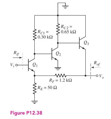
The circuit shown in Figure P12.38 is an ac equivalent circuit of a feedback amplifier. The transistor
Question:
The circuit shown in Figure P12.38 is an ac equivalent circuit of a feedback amplifier. The transistor parameters are \(h_{F E}=100\) and \(V_{A}=\infty\). The quiescent collector currents are \(I_{C 1}=14.3 \mathrm{~mA}, I_{C 2}=4.62 \mathrm{~mA}\), and \(I_{C 3}=\) \(4.47 \mathrm{~mA}\).
(a) Determine the closed-loop voltage gain \(A_{v f}=V_{o} / V_{i}\). Compare this value to the approximate ideal value of \(A_{v f} \cong\left(R_{F}+R_{E}\right) / R_{E}\).
(b) Determine the values of \(R_{i f}\) and \(R_{o f}\).

Fantastic news! We've Found the answer you've been seeking!
Step by Step Answer:
Related Book For 

Microelectronics Circuit Analysis And Design
ISBN: 9780071289474
4th Edition
Authors: Donald A. Neamen
Question Posted:


