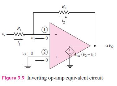
The inverting op-amp shown in Figure 9.9 has parameters (R_{1}=25 mathrm{k} Omega), (R_{2}=100 mathrm{k} Omega), and (A_{o
Question:
The inverting op-amp shown in Figure 9.9 has parameters \(R_{1}=25 \mathrm{k} \Omega\), \(R_{2}=100 \mathrm{k} \Omega\), and \(A_{o d}=5 \times 10^{3}\). The input voltage is from an ideal voltage source whose value is \(v_{I}=1.0000 \mathrm{~V}\).
(a) Calculate the closed-loop voltage gain.
(b) Determine the actual output voltage.
(c) What is the percentage difference between the actual output voltage and the ideal output voltage.
(d) What is the voltage at the inverting terminal of the op-amp?
Figure 9.9:-

Fantastic news! We've Found the answer you've been seeking!
Step by Step Answer:
Related Book For 

Microelectronics Circuit Analysis And Design
ISBN: 9780071289474
4th Edition
Authors: Donald A. Neamen
Question Posted:


