

1079 RC Circuit Analysis and Design The RC circuits in Figure P1079 represent the situation at the...
Question:
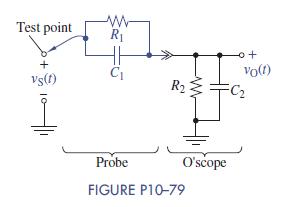
10–79 RC Circuit Analysis and Design The RC circuits in Figure P10–79 represent the situation at the input to an oscilloscope. The parallel combination of R1 and C1 represents the probe used to connect the oscilloscope to a test point. The parallel combination of R2 and C2 represents the input impedance of the oscilloscope.
(a) Assuming zero initial conditions, transform the circuit into the s domain and find the relationship between the test-point voltage VSðsÞ and the voltage VOðsÞ at the oscilloscope’s input.
(b) For R2 = 10MΩ and C2 = 5 pF, determine the values of R1 and C1 that make the input voltage a scaled duplicate of the test-point voltage.
Step by Step Answer:


The Analysis And Design Of Linear Circuits
ISBN: 9781119235385
8th Edition
Authors: Roland E. Thomas, Albert J. Rosa, Gregory J. Toussaint
