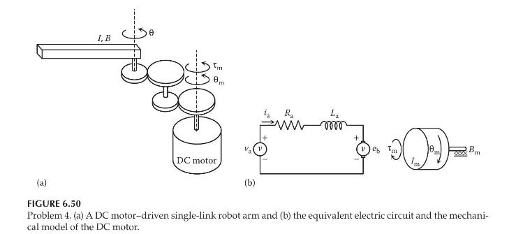
Consider the single-link robot arm, as shown in Figure 6.50a. It is driven by an armature-controlled DC
Question:
Consider the single-link robot arm, as shown in Figure 6.50a. It is driven by an armature-controlled DC motor through spur gears with a total gear ratio of \(N\) and \(\theta=N \theta_{\mathrm{m}}\). The mass moments of inertia of the motor and the load are \(I_{\mathrm{m}}\) and \(I\), respectively. The coefficients of torsional viscous damping of the motor and the load are \(B_{\mathrm{m}}\) and \(B\), respectively. Figure \(6.50 \mathrm{~b}\) shows the equivalent electric circuit and the mechanical model of the DC motor. The torque and the back emf constants of the motor are \(K_{t}\) and \(K_{e}\) respectively.
a. Determine the transfer function \(\Theta(s) / V_{\mathrm{a}}(s)\). Assume that all initial conditions are zero.
b. Determine the differential equation relating the applied voltage \(v_{\mathrm{a}}\) and the link angular displacement \(\theta\).

Step by Step Answer:

Modeling And Analysis Of Dynamic Systems
ISBN: 9781138726420
3rd Edition
Authors: Ramin S. Esfandiari, Bei Lu


