Dynamic OP AMP circuits can function as integrators or differentiators. Given an equation or graph of an
Question:
Dynamic OP AMP circuits can function as integrators or differentiators.
Given an equation or graph of an input waveform, we can predict output waveforms using the mathematical operations of integration or differentiation. Integrators and differentiators work flawlessly on ideal signal models. In practice there are some limitations caused by relatively small imperfections in real-world signals.
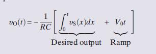
First consider an inverting integrator with an input υSðtÞ +V0, where υSðtÞ is the desired signal and V0 is a relatively small dc offset. For this input an ideal inverting integrator has an output of

The desired output is accompanied by a ramp waveform caused by a small dc offset.
Even if V0 is very small, the ramp V0t will eventually overwhelm the desired signal and saturate the OP AMP.
The dc offset problem is dealt with using the reset switch in Figure 6–25
(a) to limit the time interval during which the circuit performs integration. When the reset signal is high, the switch is closed, any voltage on the capacitor is removed, and the integrator output voltage is forced to zero. When the reset signal goes low, the switch opens and the circuit operates as an integrator. At the end of a fixed time interval, the reset signal goes high again and the switch closes, forcing the output to zero. Practical integrator applications use time-limited integration in which the integrator output is periodically reset to zero before any offset driven ramp becomes important.
Next, consider an inverting differentiator with an input υSðtÞ +VA × sinðωtÞ, where υSðtÞ is the desired signal and υA sinðωtÞ represents relatively small high-frequency noise. For this input an ideal inverting differentiator has an output of

The desired output is accompanied by an amplified noise component. Even if the input noise amplitude VA is very small, the term ωVA can be large for high-frequency noise. The basic problem is that differentiation amplifies high-frequency noise to a degree that can overwhelm the desired signal.
The high-frequency noise problem is dealt with by adding the series resistor shown in Figure 6–25(b). This addition limits the frequency range over which the circuit actually performs differentiation. At low frequencies the capacitor is the dominant element, the series resistor plays no role, and the circuit performs differentiation.
At high frequencies the roles reverse: The added resistor dominates, the capacitor can be ignored, and the circuit functions as an inverter. As a result the modified circuit only differentiates signals in a low-frequency band.2 Practical applications use band-limited differentiation to avoid high-frequency noise problems.
Step by Step Answer:

The Analysis And Design Of Linear Circuits
ISBN: 9781119235385
8th Edition
Authors: Roland E. Thomas, Albert J. Rosa, Gregory J. Toussaint


