

Figure P263 shows a voltage bridge circuit, that is, two voltage dividers in parallel with a source
Question:
Figure P2–63 shows a voltage bridge circuit, that is, two voltage dividers in parallel with a source vS. One resistor RX is variable. The goal is often to ‘‘balance’’ the bridge by making vX ¼ 0V. Derive an expression for RX in terms of the other resistors for when the bridge is balanced.AppendixLO1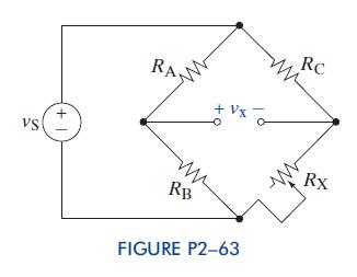
Fantastic news! We've Found the answer you've been seeking!
Step by Step Answer:

Answered By
SHAKTI KAUSHIK
I hold a Bachelor of Science in Mathematics from Govt. College University, where I graduated in 2023. During my studies, I completed coursework in advanced calculus, linear algebra, educational psychology, and teaching methods for mathematics. Following my degree, I obtained a teaching certification from the State Board of Education in 2021, which qualifies me to teach mathematics at the middle and high school levels.
My professional experience includes working as a Math Tutor at Tutoring institute since January 2020. In this role, I conduct individualized tutoring sessions for high school students, focusing on algebra and calculus. I develop personalized learning plans to address each student's unique needs and prepare them for standardized tests, such as the SAT and ACT. I also incorporate online platforms and resources to enhance the learning experience.
Furthermore, My role also involved mentoring and providing academic guidance to at-risk youth, helping them improve their problem-solving skills and build confidence in their mathematical abilities.
0 Reviews
10+ Question Solved
Related Book For 
The Analysis And Design Of Linear Circuits
ISBN: 9781118214299
7th Edition
Authors: Roland E Thomas, Albert J Rosa, Gregory J Toussaint
Question Posted:
