

The reference node and node voltages in the bridge circuit of Figure 33 are A =5V, B
Question:
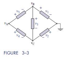
The reference node and node voltages in the bridge circuit of Figure 3–3 are υA =5V,
υB = 10 V, and υC = −3 V. Find the element voltages
Fantastic news! We've Found the answer you've been seeking!
Step by Step Answer:

Answered By
Albert Kinara
i am an expert research writer having worked with various online platform for a long time. i also work as a lecturer in business in several universities and college part time and assure you well researched and articulate papers. i have written excellent academic papers for over 5 year and have an almost similar experience experting many clients in different units. bachelor of commerce (finance)
masters in strategic management
phd finance
26+ Reviews
48+ Question Solved
Related Book For 
The Analysis And Design Of Linear Circuits
ISBN: 9781119235385
8th Edition
Authors: Roland E. Thomas, Albert J. Rosa, Gregory J. Toussaint
Question Posted:
