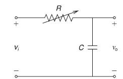
An RC circuit used to produce time delay is shown in Figure 10.40. For a step input
Question:
An RC circuit used to produce time delay is shown in Figure 10.40. For a step input voltage \(\mathrm{v}_{\mathrm{i}}(\mathrm{t})=2 \mathrm{u}(\mathrm{t})\) and \(\mathrm{C}=10 \mu \mathrm{F}\), determine \(\mathrm{T}_{\text {delay }}\) for the following cases:
(a) \(\mathrm{R}=100 \mathrm{k} \Omega\); and
(b) \(\mathrm{R}=1 \mathrm{M} \Omega\). Sketch the output \(\mathrm{v}_{\mathrm{o}}(\mathrm{t})\) versus time for cases (a) and (b).

Step by Step Answer:
Related Book For 

Power System Analysis And Design
ISBN: 9781305632134
6th Edition
Authors: J. Duncan Glover, Thomas Overbye, Mulukutla S. Sarma
Question Posted:


