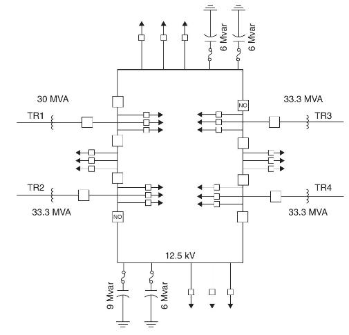
As shown in Figure 14.24, an urban distribution substation has one 30-MVA (FOA) and three 33.3 MVA
Question:
As shown in Figure 14.24, an urban distribution substation has one 30-MVA (FOA) and three 33.3 MVA (FOA), \(138 \mathrm{kV} \Delta / 12.5 \mathrm{kV}\) Y transformers denoted TR1-TR4, which feed through circuit breakers to a ring bus. The transformers are older transformers designed for \(55^{\circ} \mathrm{C}\) temperature rise. The ring bus contains eight bus-tie circuit breakers, two of which are normally open (NO), so as to separate the ring bus into two sections. TR 1 and TR 2 feed one section, and TR 3 and TR 4 feed the other section. Also, four capacitor banks, three banks rated at 6 Mvar and one at 9 Mvar, are connected to the ring bus. Twenty-four \(12.5-\mathrm{kV}\) underground primary feeders are served from the substation, 12 from each section. The utility that owns this substation has the following transformer summer loading criteria based on a percentage of nameplate rating:
a. \(120 \%\) for normal summer loading.
b. \(150 \%\) during a two-hour emergency.
c. \(130 \% 30\)-day emergency loading.
Determine the following summer ratings of this substation:
(a) the normal summer rating with all four transformers in service;
(b) the allowable substation rating assuming the single-contingency loss of one transformer; and
(c) the 30-day emergency rating under the single-contingency loss of one transformer. Assume that during a two-hour emergency, switching can be performed to reduce the total substation load by \(10 \%\) and to approximately balance the loadings of the three transformers remaining in service. Assume a 5\% reduction for unequal transformer loadings.

Step by Step Answer:

Power System Analysis And Design
ISBN: 9781305632134
6th Edition
Authors: J. Duncan Glover, Thomas Overbye, Mulukutla S. Sarma


