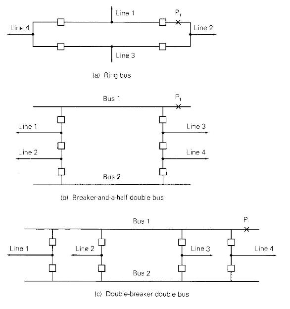
Figure 10.46 shows three typical bus arrangements. Although the number of lines connected to each arrangement varies
Question:
Figure 10.46 shows three typical bus arrangements. Although the number of lines connected to each arrangement varies widely in practice, four lines are shown for convenience and comparison. Note that the required number of circuit breakers per line is 1 for the ring bus, \(1 \frac{1}{2}\) for the breaker-and-a-half double-bus, and 2 for the double-breaker double-bus arrangement. For each arrangement:
(a) Draw the protective zones.
(b) Identify the breakers that open under primary protection for a fault on line 1.
(c) Identify the lines that are removed from service under primary protection during a bus fault at \(\mathrm{P}_{1}\).
(d) Identify the breakers that open under backup protection in the event a breaker fails to clear a fault on line 1 (that is, a stuck breaker during a fault on line 1).

Step by Step Answer:

Power System Analysis And Design
ISBN: 9781305632134
6th Edition
Authors: J. Duncan Glover, Thomas Overbye, Mulukutla S. Sarma


