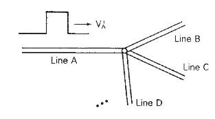
Referring to Figure 13.3, the source voltage at the sending end is a step (e_{mathrm{G}}(t)=mathrm{Eu}_{-1}(t)) with an
Question:
Referring to Figure 13.3, the source voltage at the sending end is a step \(e_{\mathrm{G}}(t)=\mathrm{Eu}_{-1}(t)\) with an inductive source impedance \(\mathrm{Z}_{\mathrm{G}}(s)=s \mathrm{~L}_{\mathrm{G}}\), where \(\mathrm{L}_{\mathrm{G}} / \mathrm{Z}_{c}=\tau / 3\). At the receiving end, \(\mathrm{Z}_{\mathrm{R}}=\mathrm{Z}_{c} / 4\). The line and source inductance are initially unenergized.
(a) Draw the Bewley lattice diagram for \(0 \leq t \leq 5 \tau\).
(b) Plot \(v(l, t)\) versus time \(t\) for \(0 \leq t \leq 5 \tau\).
Figure 13.3

Step by Step Answer:
Related Book For 

Power System Analysis And Design
ISBN: 9781305632134
6th Edition
Authors: J. Duncan Glover, Thomas Overbye, Mulukutla S. Sarma
Question Posted:


