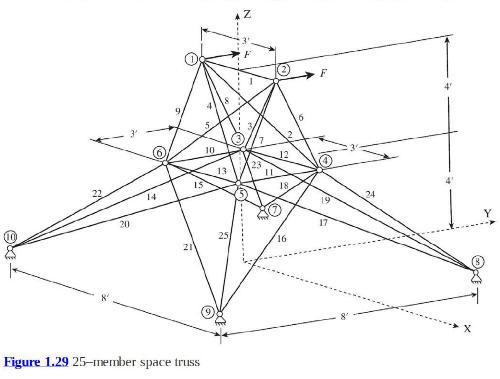
A space frame structure as shown in figure 1.29 consists of 25 truss members. Initially, all members
Question:
A space frame structure as shown in figure 1.29 consists of 25 truss members. Initially, all members have the same circular crosssections with diameter \(d=2.0 \mathrm{in}\). At nodes 1 and 2, a constant force \(F=60,000 \mathrm{lb}\). is applied in the \(y\) direction. Four nodes \((7,8,9\), and 10\()\) are fixed on the ground. The frame structure is made of a steel material whose properties are Young's modulus \(E=3 \times 10^{7}\) psi, Poisson's ratio \(v=0.3\), yield stress \(\sigma_{Y}=37,000 \mathrm{psi}\), and density \(ho=0.284 \mathrm{lb}\)./in \({ }^{3}\). The safety factor \(N=1.5\) is used. Due to the manufacturing constraints, the diameter of the truss members should vary between \(0.1 \mathrm{in}\). and \(2.5 \mathrm{in}\).
i) Solve the initial truss structure using truss finite elements. Provide a plot that shows labels for elements and nodes along with boundary conditions. Provide deformed geometry of the structure and a table of stress in each element.
ii) Minimize the structural weight by changing the cross-sectional diameter of each truss element, while all members should be safe under the given yield stress and the safety factor. You can use the symmetric geometry of the structure. Identify zero force members. For zero force members, use the lower bound of the cross-sectional diameter. Provide deformed geometry at the optimum design along with a table of stress at each element. Provide structural weights of initial and optimum designs.

Step by Step Answer:

Introduction To Finite Element Analysis And Design
ISBN: 9781119078722
2nd Edition
Authors: Nam H. Kim, Bhavani V. Sankar, Ashok V. Kumar


