An air-to-water compact heat exchanger is to be designed to serve as an intercooler for a 5,000
Question:
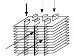
An air-to-water compact heat exchanger is to be designed to serve as an intercooler for a 5,000 hp gas turbine plant. The exchanger is to meet the following heat transfer and pressure drop performance specificationsAir-side Operating ConditionsFlow rate 200,000 lb/h (25.2 kg/s)Inlet Temperature 720 R (400 K)Outlet Temperature 540 R (300 K)Inlet Pressure(p1) 29.7 psia (2.05 x 10⁵ N/m2)Pressure Drop Ratio (Dp/p1) 7.6%Water-side Operating ConditionsFlow rate 400,000 lb/h (50.4 kg/s)Inlet Temperature 520 R (289 K)The exchanger is to have a cross-flow configuration with both fluids unmixed. The heat exchanger surface proposed for the exchanger consists of flattened tubes with continuous aluminum fins specified as a 11.32?? 0.737 ?? SR surface in Ref. 10. The heat exchanger is shown schematically below.

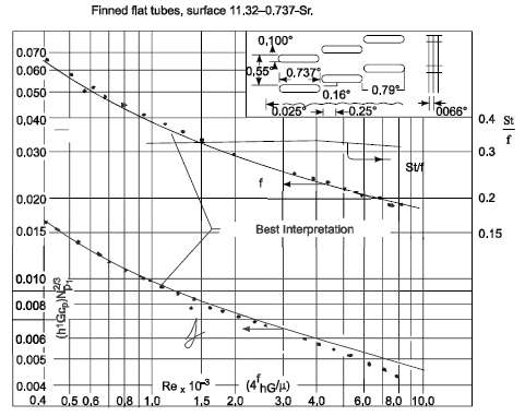
The measured heat transfer and friction characteristic for this exchanger surface are shown in the graph below

Geometrical details for the proposed surface areAir-side Flow passage hydraulic radius (rh) = 0.00288 ft (0.0878 cm)Total transfer area/total volume (aair) = 270 ft2/ft3 (886 m2/m3)Free flow area/frontal area (s) = 0.780Fin area/total area (At/A) = 0.845Fin metal thickness (t) = 0.00033 ft (0.0001 m)Fin length (1/2 distance between tubes, Lf) = 0.225 in (0.00572 m)Water side Tubes as given in Problem 8.53Water-side transfer area/total volume (aH2O) = 42.1 ft2/ft3The design should specify the core size, the air flow frontal area, and the flow length. The water velocity inside the tubes is 4.4 ft/s (1.34 m/s). See problem 8.53 for the calculation of the water side heat transfer coefficient. Note: (i) the free-flow area is defined such that the mass velocity, G, is the air mass flow rate per unit free flow area, (ii) the core pressure drop is given by ??p = fG2L/2ρrh where L is the length of the core in the air flow direction, (iii) the fin length, Lf, is defined such that Lf = 2A/P where A is the fin cross-sectional area for heat conduction and P is the effective fin perimeter.GIVENAir-to-Water Intercooler with the geometry and requirements specified aboveFrom Problem 8.53: Water side convective heat transfer coefficient (hc,H2O) = 7580 W/(m2 K)ASSUMPTIONSSteady stateEntrance effects are negligibleFlow acceleration effects are negligibleNegligible fouling resistanceNegligible variation in thermal resistanceThe thermal resistance of the tube wall isnegligible
Step by Step Answer:

Principles of heat transfer
ISBN: 978-0495667704
7th Edition
Authors: Frank Kreith, Raj M. Manglik, Mark S. Bohn


