All Matches
Solution Library
Expert Answer
Textbooks
Search Textbook questions, tutors and Books
Oops, something went wrong!
Change your search query and then try again
Toggle navigation
FREE Trial
S
Books
FREE
Tutors
Study Help
Expert Questions
Accounting
General Management
Mathematics
Finance
Organizational Behaviour
Law
Physics
Operating System
Management Leadership
Sociology
Programming
Marketing
Database
Computer Network
Economics
Textbooks Solutions
Accounting
Managerial Accounting
Management Leadership
Cost Accounting
Statistics
Business Law
Corporate Finance
Finance
Economics
Auditing
Hire a Tutor
AI Study Help
New
Search
Search
Sign In
Register
study help
engineering
geological engineering
Questions and Answers of
Geological Engineering
Given a cylindrical sandstone laboratory test specimen of diameter D and height L subjected to a vertical load F (force), find (a) Te forces N and T acting normal and tangential to a surface
Given a rectangular prism of edge length D and height L subjected to a vertical load F (force) applied to the prism ends and a horizontal pressure p applied to the sides of the prism, find (a) the
Is the following equation a physical law, kinematic relationship, or material law? Ms = ∫v rdm Here M =mass in volume V, dm = a mass element, r = position vector of dm, and s is the
Is the following equation a physical law, kinematic relationship, or material law? ˙σ = ∂σ / ∂t
Darcy’s law for fluid flow in porous media relates the seepage velocity v to the hydraulic gradient h through a constant k (hydraulic conductivity). Thus, v = kh Is this relationship a physical
Consider a “two-dimensional” state of stress in the x–y plane characterized by: σxx = 2,500 σyy = 5,200 τxy = 3,700
Given the stress state in Problem 1.11, find: the magnitude and direction of the maximum shear stress and illustrate with a sketch.
Consider a “two-dimensional” state of stress in the x–y plane characterized by: σxx = 17.24 σyy = 35.86 τxy = 25.52 Where units are MPa and tension is positive. Find: the
Given the stress state in Problem 1.13, find: the magnitude and direction of the maximum shear stress and illustrate with a sketch
Suppose that σxx = 2,500 σyy = 5,200 τxy = 3,700 and the z-direction shear stresses (τzx, τzy) are zero, while the z-direction normal stress (σzz) is 4,000 psi.
With reference to Problem 1.15, find the magnitude of the maximum shear stress and show by sketch the orientation of the plane it acts on.
Suppose that σxx = 17.24 σyy = 35.86 τxy = 25.52 in MPa and the z-direction shear stresses (τzx, τzy) are zero, while the z-direction normal stress (σzz) is 27.59 MPa.
With reference to Problem 1.17, find the magnitude of the maximum shear stress and show by sketch the orientation of the plane it acts on.
Consider a “two-dimensional” state of stress in the x–y plane characterized by: σxx = 5,200 σyy = 2,500 τxy = −3,700 where units are psi and tension is positive. Find: the
Consider a “two-dimensional” state of stress in the x–y plane characterized by: σxx = 35.86 σyy = 17.24 τxy = −25.52 Where units are MPa and tension is positive. Find:
Consider a three-dimensional state of stress characterized by: σxx = 3,000 σyy = 2,000 τxy = 0. σzz = 4,000 τzx = 0. τyz = 2,500 where units are psi and compression
Given the stress state in Problem 1.21, find the state of stress relative to axes abc(σaa, . . . , τca) rotated 30◦ counterclockwise about the z-axis
Consider a three-dimensional state of stress characterized by: σxx = 20.69 σyy = 13.79 τxy = 0.0 σzz = 27.59 τzx = 0.0 τyz = 17.24 Where units are MPa and
Given the stress state in Problem 1.23, find the state of stress relative to axes abc(σaa, . . . , τca) rotated 30◦ counterclockwise about the z-axis.
Show in two dimensions that the mean normal stress σm = (σxx +σyy)/2 is invariant under a rotation of the reference axes and is equal to one-half the sum of the major and minor
Show in two dimensions that the maximum shear stress τm = {[(σxx − σyy)/2]2 + (τxy)2}(1/2) is invariant under a rotation of the reference axes and is equal to one-half the
Consider an NX-size drill core (2-1/8 in., 5.40 cm diameter) with an L/D ratio (length to diameter) of two under an axial load of 35,466 pounds (158.89 kN). Find: 1 The state of stress within the
Strain measurements are made on a wide, flat bench in a dimension stone quarry using a 0-45-90 rosette. The 0-gauge is oriented N60E. Specific weight of the stone (a granite) is 162 pcf (25.6 kN/m3);
Given the stresses in psi: σxx = 1,500 σyy = −2,000 σzz = 3,500 τxy = 600 τyz = −300 τzx = −500 Where x = east, y = north, z = up, compression is
Given the stresses in MPa: σxx = 10.35 σyy = −13.79 σzz = 24.14 τxy = 4.14 τyz = −2.07 τzx = −3.45 where x = east, y = north, z = up, compression is
Given the strains: εxx = 2,000 εyy = 3,000 εzz = 4,500 γxy = −200 γyz = 300 γzx = 225 Where x = east, y = north, z = up, compression is positive, the units
Consider a cylindrical test specimen under a confining pressure of 3,000 psi and an axial stress of 3,000 psi with compression positive, so that in cylindrical coordinates σzz = 3,000 σrr
Given the strains: εxx = 2,000 εyy = 3,000 εzz = 4,500 γxy = −200 τyz = 300 γzx = 225 Where x = east, y = north, z = up, compression is positive, the units
Consider a cylindrical test specimen under a confining pressure of 20.69 MPa and an axial stress of 20.69 MPa with compression positive, so that in cylindrical coordinates σzz = 20.69 σrr
Show that under complete lateral restraint and gravity loading only, that the vertical normal stress in a homogeneous, isotropic linearly elastic earth at a depth z measured from the surface with
Suppose an NX-size test cylinder with an L/D ratio of two has a Young’s modulus of 10 million psi, a Poisson’s ratio of 0.35 and fails in uniaxial compressive at 0.1% strain. Find: 1 The axial
Suppose an NX-size test cylinder with an L/D ratio of two has a Young’s modulus of 68.97 GPa, a Poisson’s ratio of 0.35, and fails in uniaxial compressive at 0.1% strain. Find:Br> 1 The axial
Consider gravity loading under complete lateral restraint in flat, stratified ground where each stratum is homogeneous, isotropic, and linearly elastic. Assume compression is positive, ν is
Consider gravity loading only under complete lateral restraint in flat strata with properties given in Table 1.2. Vertical stress at the top of the geologic column given in Table 1.2 is 1,000 psi.
Consider gravity loading only under complete lateral restraint in flat strata with properties given in Table 1.3. Vertical stress at the top of the geologic column given in Table 1.3 is 6.9 MPa.
A stress measurement made in a deep borehole at a depth of 500 m (1,640 ft) indicates a horizontal stress that is three times the vertical stress and that the vertical stress is consistent with an
Identify the three major categories of equations that form the “recipe” for calculating rock mass motion. Give an example of each in equation form.
If ρ is mass density, explain why or why not the conservation of mass may be expressed as M = ∫v ρdV For a body of mass M occupying volume V
Name the two types of external forces recognized in mechanics and give an example of each.
A huge boulder is inadvertently cast high into the air during an open pit mine blast. Using the definition of mass center and Newton’s second law of motion, show that the center of mass of the
Suppose a static factor of safety is defined as the ratio of resisting to driving forces, that is, FS = R/D. Show that a factor of safety less than one implies acceleration is impending
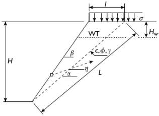
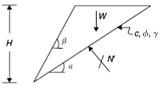
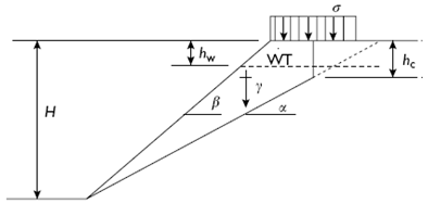
Derive an expression for the factor of safety FS for a planar block slide with a tension crack behind the crest. The slope height is H and has a face angle β measured from the horizontal to the
Modify the expression for the safety factor from Problem 2.1 to include the effect of a water force P acting on the inclined failure surface. Note that the water table is below the bottom of the
With reference to Problem 2.2, suppose the water pressure p increases linearly with depth (according to p = γwz where z = depth below water table and γw = specific weight of water) from the water
Consider a seismic load effect S that acts horizontally through the slide mass center with an acceleration as given as a decimal fraction a0 of the acceleration of gravity g (as = a0g, typically a0 =
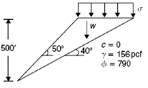
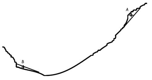
Given the planar block slide data shown in the sketch where a uniformly distributed surcharge ? is applied to the slope crest over an area (bl), first find the slope safety factor without a surcharge
Consider the planar block slide in the sketch. If no surcharge is present, find the maximum depth H of excavation possible before failure impends.
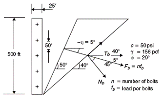
Suppose the slope in the sketch is cable bolted. No surcharge is present. Bolt spacing is 50 ft (15.2 m) in the vertical direction and 25 ft (7.6 m) in the horizontal direction. Bolts assemblages are
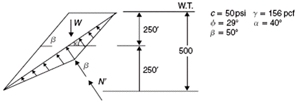
Consider the planar block slide in sketch without surcharge, seismic load, and bolt reinforcement and suppose the water table rises to the top of the slide. Find the safety factor of the
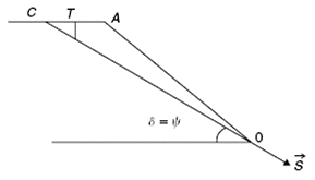
Suppose the cohesion of the slide mass shown in the sketch decreases to zero and no surcharge, seismic load, or water is present. Determine whether the slide mass will accelerate, and if so, the
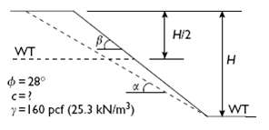
Some data for a possible planar block slide are given in the sketch. If ? = 35?, ? = 45?, and H = 475 ft (145 m), what cohesion c (psf, kPa) is needed to give a safety factor of at least 1.5?
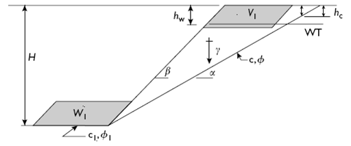
Consider the planar block slide in the sketch. (a) Show algebraically that reduction of the slide mass volume from Vo to V1 by excavating a relieving bench near the crest necessarily increases
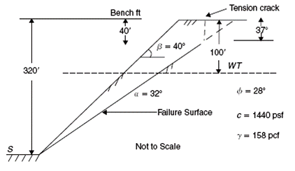
With reference to the sketch, if no tension crack is present, α = 29◦, γ = 156pcf (24.7kN/m3), joint persistence = 0.87, no crest relieving bench and no toe berm are being considered,
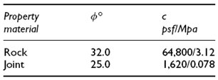
A generic diagram of a slope in a jointed rock mass that is threatened by a planar block slide is shown, in the sketch. Although not shown, bench height is 55 ft (16.76 m).Given that Mohr–Coulomb
A generic diagram of a slope in a jointed rock mass that is threatened by a planar block slide is shown in the sketch. A minimum safety factor of 1.05 is required. Although not shown bench height is
Given the following planar block slide data: Mohr–Coulomb failure criterion applies1 slope height H =
A generic diagram of a slope in a jointed rock mass that is threatened by a planar block slide is shown in the sketch. With neglect of any seismic load, find the slope height (pit depth) possible
With reference to the sketch of the potential slope failure shown in the sketch, find:
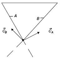
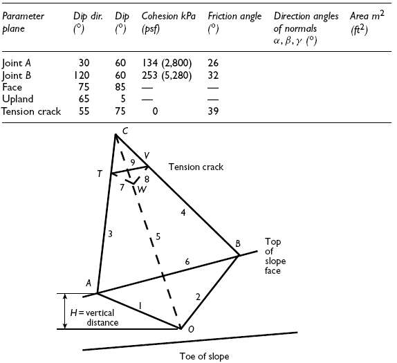
Given the data in Table 2.7, determine the direction angles of the normal vectors to joint planes A andB.
Calculate the dip and dip direction of the line of intersection of joint planes A and B, then sketch the result in compass coordinates.
Given that the vertical distance between points a and d is 120 ft (36.6 m), determine the areas of joint planes A and B, assuming no tension crack is present.
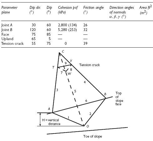
Use computer programs to verify the area data in Table 2.7 with a tension crack present and a rock specific weight of 158pcf (25.0kN/m3). What is the wedge safety factor when the water table is below
With reference to the generic wedge in the sketch and the specific data in Table 2.8 if the safety factor with respect to sliding down the line of intersection is greater than 1.10, then safety is
Two joints K1 and K2 are mapped in the vicinity of a proposed surface mine. Joints in set K1 have dip directions of 110◦ and dips of 38◦; joints in set K2 have dip directions of 147◦ and dips
With reference to the generic wedge shown in the sketch and the data in Table 2.9, the water table is below the toe, vertical distance between A and O is 85 ft (25.9 m), point T is 40 ft from point
With reference to the wedge shown in the sketch and the Table 2.10 data, if the safety factor with respect to sliding down the line of intersection is greater than 1.10, then safety is assured. Can
Given the wedge data in Table 2.11, if the vertical distance between crest and the point where the line of intersection between the joint planes intersects the face is 120 ft (36.6 m), find the dip
With reference to the generic wedge shown in the sketch and the data in Table 2.12, the water table is below the toe, vertical distance between A and O is 25.9 m (85 ft),point T is 12.2 m (40 ft)
Consider a bank 40 ft (12.2 m) high with a slope of 30? that may fail by rotation on a slip circle of radius 60 ft (18.3 m) with center at (20, 48 ft) or (6.10, 14.63 m) relative to coordinates in ft
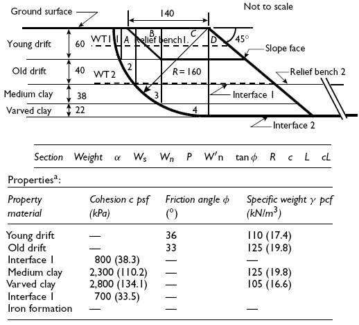
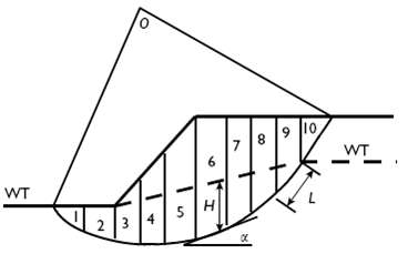
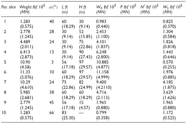
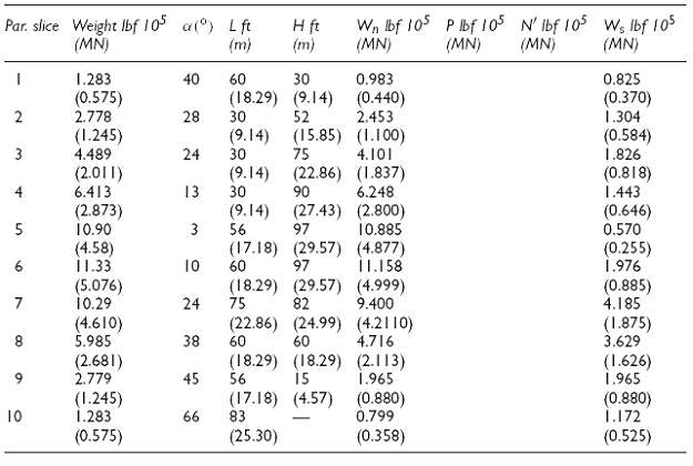
With reference to the sketch and tables, find the safety factors for the four cases posed using the method of slices. Include all important calculations. If you use a spreadsheet, include suitable
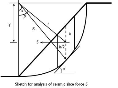
With reference to the sketch illustrating a rotational slide being considered for a method of slices stability analysis, show that the inclusion of seismic forces as quasistatic horizontal forces
Given the potential one-foot thick slope failure along the circular arc (R = 300 ft, 91.44 m) shown in the sketch, the data in Table 2.14, a slope height = 120 ft (36.6 m); slope angle = 29?,
Given the potential one-foot thick slope failure along the circular arc (R = 300 ft, 91.44 m) shown in the sketch and the data in Table 2.14, find the safety factor possible with drawdown of the
Given the potential one-foot thick slope failure along the circular arc shown in the sketch and the data in Table 2.14, find the safety factor for slice 2 and for slice 7, then show algebraically the
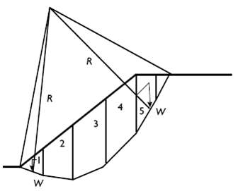
Given the circular failure illustrated in the sketch, find algebraically the factor of safety. Assume that the material properties and geometry of slope and slices areknown.
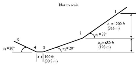
Consider the possibility of a rock slide starting at point A and ending at B, as shown in the sketch, and suppose the slide is driven by gravity and resisted by friction. Derive expressions for
Given the slope profile in vertical section shown in the sketch and an angle of friction ? = 15?, if the mass center of the slide is initially at 1, determine the height of the mass center after
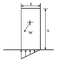
Toppling of tall blocks is possible when one corner tends to lift off from the base supporting the block, as shown in the sketch. Show that the block is stable provided tan(?)
A rock block with a square base rests on a 28◦ slope. The block base plane has a friction angle of 32◦. There is no adhesion between block and base plane. Find the base dimensions necessary to
A 20 foot diameter circular shaft is planned in a massive rock. Laboratory tests on core from exploration drilling show thatCo = 22,000 psi To = 1,200 psiγ =
If the opening in Problem 1 is in an in situ stress field such that σh = σv, what are the safety factors?
If the opening in Problem 1 is in an in situ stress field such that σh = 0.01σv, is there a possibility of failure? Justify your answer.
A 6 m diameter circular shaft is planned in massive rock. Laboratory tests on core from exploration drilling show thatCo = 152 MPa To = 8.3MPaγ = 23kN/m3 E = 34.5GPaG = 13.8GPaDepth is 915 m. Site
If the opening in Problem 4 is in an in situ stress field such that σh = σv, what are the safety factors?
If the opening in Problem 4 is in an in situ stress field such that σh = 0.01σv, is there a possibility of failure? Justify your answer.
Which is preferable from the rock mechanics viewpoint: an elliptical, ovaloidal, or rectangular opening of Wo/Ho of 2 for a stress field M = 1/3? M = 0? Justify your choices.
A rectangular shaft 10 ft wide by 20 ft long is sunk vertically in ground where the state of premining stress is σxx = 1,141, σyy = 2,059, σzz = 1,600, τxy = 221, τyz = 0, τzx = 0, with
A rectangular shaft 3 m wide by 6 m long is sunk vertically in ground where the state of premining stress is σxx = 7.9, σyy = 14.2, σzz = 11.0, τxy = 1.5, τyz = 0, τzx = 0, with compression
A 12 ft by 24 ft rectangular shaft is sunk to a depth of 3,000 ft in ground where the premining stress field is given by formulas Sv = 1.2h, Sh = 120 + 0.5h, SH = 3, 240 + 0.3h where h is depth in
A 3.66 m by 7.32 m rectangular shaft is sunk to a depth of 914 m in ground where the premining stress field is given by formulas Sv = 27.2h, Sh = 826 + 11.3h, SH = 22, 345 + 6.8h where h is depth in
Thin overburden is scrapped to expose fresh bedrock at the site of a planned shaft. A 0-45-90 strain gauge rosette is bonded to the bedrock after a five inch square portion of the surface is ground
With reference to Problem 12, if the state of stress at the surface continues to depth in addition to gravity load, and the specific weight of rock is 28kN/m3, what strengths are needed at a depth of
Thin overburden is scrapped to expose fresh bedrock at the site of a planned shaft. A 0-45-90 strain gauge rosette is bonded to the bedrock after a 12.7 cm square portion of the surface is ground
With reference to Problem 14, if the state of stress at the surface continues to depth in addition to gravity load, and the specific weight of rock is 28kN/m3, what strengths are needed at a depth of
If the premining stress state in Problem 16 where hydrostatic (3D), what shape would be more favorable, an ellipse, rectangle, or ovaloid (with semi-axes ratio of 2)?
If the premining stress state in Problem 18 where hydrostatic (3D), what shape would be more favorable, an ellipse, rectangle, or ovaloid (with semi-axes ratio of 2)?
A rectangular shaft 18 ft by 24 ft is planned for a depth of 4,800 ft where the premining stresses relative to compass coordinates (x = east, y = north, z = up) are given by: σxx = 250 + 0.5h, σyy
Showing 1 - 100
of 335
1
2
3
4