New Semester
Started
Get
50% OFF
Study Help!
--h --m --s
Claim Now
Question Answers
Textbooks
Find textbooks, questions and answers
Oops, something went wrong!
Change your search query and then try again
S
Books
FREE
Study Help
Expert Questions
Accounting
General Management
Mathematics
Finance
Organizational Behaviour
Law
Physics
Operating System
Management Leadership
Sociology
Programming
Marketing
Database
Computer Network
Economics
Textbooks Solutions
Accounting
Managerial Accounting
Management Leadership
Cost Accounting
Statistics
Business Law
Corporate Finance
Finance
Economics
Auditing
Tutors
Online Tutors
Find a Tutor
Hire a Tutor
Become a Tutor
AI Tutor
AI Study Planner
NEW
Sell Books
Search
Search
Sign In
Register
study help
engineering
geological engineering
Design Analysis in Rock Mechanics 1st edition William G. Pariseau - Solutions
Considering the data and results from Problem 20, determine the shaft wall safety factors in tension and compression.
Given the stresses relative to compass coordinates (x = east, y = north, z = sup), σxx = 2,155, σyy = 3,045, σzz = 4,200, τyx = −1,222, τxz = 0, τyz = 0 in psi with compression positive, find the principal stresses σ1, σ2, σ3 (magnitude and orientation). Show with a suitable sketch. Then
A rectangular shaft 6 × 8 m is planned for a depth of 1,500 m where the premining stresses relative to compass coordinates (x=east, y =north, z = up) are given by: σxx = 1,724 + 11.3h, σyy = 5,517 + 4.5h, σzz = 2.49h, where h is depth in meters and stress is in kPa; compression is positive.
Considering the data and results from Problem 23, determine the shaft wall safety factors in tension and compression.
Given the stresses relative to compass coordinates (x=east, y=north, z =up), σxx = 14.9, σyy = 21.0, σzz = 29.0, τyx = −8.4, τxz = 0, τyz = 0 in MPa with compression positive, find the principal stresses σ1, σ2, σ3 (magnitude and orientation). Show with a suitable sketch. Then consider
A large vertical shaft is planned for an underground hard rock mine. Laboratory tests on core from exploration drilling show thatCo = 21,500 psi, To = 1,530 psi, E = 6.25(106) psi,G = 2.5(106) psi, γ = 144pcfwhile premining stress measurements can be fit to the formulasSE = 200 + 0.3h, SN = 600 +
A large vertical shaft is planned for an underground hard rock mine. Laboratory tests on core from exploration drilling show thatCo = 148.3, To = 10.6, E = 43.10GPa, G = 17.24GPa,γ = 22.78kN/m3 while premining stress measurements can be fit to the formulas SE = 1,379 + 6.8h, SN = 4,138 + 20.4h, SV
Laboratory tests on core from exploration drilling show thatCo = 21,500 psi, To = 1,530, E = 6.25(106) psi,G = 2.5(106) psi, γ = 144pcf, while premining stress measurements can be fit to the formulas SE = 200 + 0.3h, SN = 600 + 0.9h, SV = 1.1h, where E,N, V refer to compass coordinates (x=east,
A rectangular shaft 12 ft by 24 ft is planned for deepening from a depth of 3,200 to 4,800 ft in ground where the pre-shaft stress state relative to compass coordinates (x = east, y = north, z = up) is given by Sxx = 2, 000 + 1.1d, Syy = 50 + 0.9d, Szz = 1.15d, Txy = −350 − 0.3d, Tyz = 0.0, Tzx
Laboratory tests on core from exploration drilling show thatCo = 148.3 MPa, To = 10.55 MPa, E = 43.10GPa,G = 17.24GPa, γ = 22.78kN/m3, while premining stress measurements can be fit to the formulasSE = 1,379 + 6.8h, SN = 4,138 + 20.4h, SV = 24.9h where E, N, V refer to compass coordinates (x =
A rectangular shaft 3.7 × 7.4 m is planned for deepening from a depth of 975 to 1,463 m in ground where the pre-shaft stress state relative to compass coordinates (x = east, y = north, z = up) is given (in kPa) by Sxx = 13,793 + 24.9d, Syy = 345 + 20.4d, Szz = 26.0d, Txy = −2,414 − 6.8d, Tyz =
A vertical circular shaft will pass through a water bearing stratum at a depth of 2,780 ft where the water pressure is estimated to be 210 psi. Finished shaft diameter must be 18 ft. The pre-shaft stress state is attributable to gravity alone. Rock properties are: Co = 6,750 psi, To = 675 psi, E =
A three-compartment rectangular shaft 12 × 24 ft in cross section is planned for a depth of 3,000 ft. The pre-sinking stress field is assumed to be caused by gravity only. The weakest rock along the proposed shaft route has an unconfined compressive strength of 8,000 psi and a tensile strength of
The pre-sinking stress field assumed to be caused by gravity alone (Problem 3.33) turns out to be wrong. The actual stress field has a tectonic component that adds a constant 1,250 psi to the east–west horizontal stress attributable to gravity and twice that amount to the north–south stress
A circular shaft 18 ft in diameter is decided upon rather than the proposed rectangular shaft. Determine the unlined shaft wall safety factors. Note: The stress field from Problem 3.34 applies.
The in situ stress field for Problems 34 and 35 changes between 3,000 and 3,500 ft to one described by the formulas σv = 1.125h, σH = 3,500 + 0.33h, σh = 3,500 + 0.33h, where the stresses are in psi and the depth h is in ft. The stresses σv, σH, σh are principal stresses in the vertical and
A three-compartment rectangular shaft 3.7 × 7.4 m in cross section is planned for a depth of 914 m. The pre-sinking stress field is assumed to be caused by gravity only. The weakest rock along the proposed shaft route has an unconfined compressive strength of 55.17 MPa and a tensile strength of
The pre-sinking stress field assumed to be caused by gravity alone (Problem 3.37) turns out to be wrong. The actual stress field has a tectonic component that adds a constant 8.62 MPa to the east–west horizontal stress attributable to gravity and twice that amount to the north–south stress
A circular shaft 5.5min diameter is decided upon rather than the proposed rectangular shaft. Determine the unlined shaft wall safety factors. Note: The stress field from Problem 3.38 applies.
The in situ stress field for Problems 38 and 39 changes between 914 and 1,067 m to one described by the formulas σv = 25.45h, σH = 24,138 + 7.47h, σh = 24,138 + 7.47h where the stresses are in kPa and the depth h is in m. The stresses σv, σH, σh are principal stresses in the vertical and
A circular shaft liner is sunk to a depth of 3,750 ft (1,143 m). If the premining stress field is caused by gravity alone, what unconfined compressive rock strength in psi (MPa) is needed for a rock factor of safety of 3.0?
A circular vertical shaft is planned to have a finished, inside diameter of 19 ft in an underground hard rock mine. Rock properties are: Co = 23,700 psi, To = 1,480 psi, E = 5.29(106 psi), ν = 0.27, γ = 162pcf. The premining stress state relative to compass coordinates is:SE = 350 + 0.2h, SN =
With reference to the previous problem data, if changes in the inside diameter of the lined shaft are monitored for safety, what “reading” in inches would indicate impending failure of the liner?
A circular vertical shaft is planned to have a finished, inside diameter of 5.8 m in an underground hard rock mine. Rock properties are: Co = 163.5 MPa, To = 10.21 MPa, E = 36.48GPa, ν = 0.27, γ = 25.63kN/m3. The premining stress state relative to compass coordinates is: SE = 2,414 + 4.53h, SN =
With reference to the previous problem data, if changes in the inside diameter of the lined shaft are monitored for safety, what “reading” in centimeters would indicate impending failure of the liner?
A circular vertical shaft is planned to have a finished, inside diameter of 26 ft in an underground hard rock mine. Rock properties are: Co = 27,400 psi, To = 1,840 psi, E = 6.19(106 psi), ν = 0.22, γ = 159pcf. The premining stress state relative to compass coordinates is: SE = 600 + 0.3h, SN =
With reference to the previous problem data, if changes in the inside diameter of the lined shaft are monitored for safety, what “reading” in inches would indicate impending failure of the liner?
A circular vertical shaft is planned to have a finished, inside diameter of 8 m in an underground hard rock mine. Rock properties are: Co = 189.0 MPa, To = 12.69 MPa, E = 42.69GPa, ν = 0.22, γ = 25.15kN/m3. The premining stress state relative to compass coordinates is: SE = 4,138 + 6.79h, SN =
With reference to the previous problem data, if changes in the inside diameter of the lined shaft are monitored for safety, what “reading” in cm would indicate impending failure of the liner?
A vertical unlined 22 ft diameter circular shaft is fitted with a concrete shaft liner to withstand water pressure of 123 psi in a massive sandstone aquifer at a depth of 2,890 ft. Liner properties are: E = 3.5 million psi, ν = 0.30, Co = 4,500 psi, To = 450 psi, γ = 152pcf. A liner safety factor
Show why the weight of a concrete shaft liner that is poured to the walls of the unlined shaft is not important to liner stress
A large vertical finished (inside) shaft diameter of 32 ft is required for hoisting capacity in a planned high volume underground oil shale mine. An aquifer is encountered at a depth of 1,270 ft where the water pressure is 240 psi.(a) Determine the thickness of a concrete liner needed for a liner
A vertical circular shaft will pass through a water-bearing stratum at a depth of 2,780 ft where the water pressure is estimated to be 210 psi. Finished shaft diameter must be 18 ft. The pre-shaft stress state is attributable to gravity alone. Rock properties are: Co = 6,750 psi, To = 675 psi, E =
A large vertical finished (inside) shaft diameter of 9.75mis required for hoisting capacity in a planned high volume underground oil shale mine. An aquifer is encountered at a depth of 387 m where the water pressure is 1.66 MPa.(a) Determine the thickness of a concrete liner needed for a liner
A vertical circular shaft will pass through a water-bearing stratum at a depth of 847 m where the water pressure is estimated to be 1.45 MPa. Finished shaft diameter must be 5.5 m. The pre-shaft stress state is attributable to gravity alone. Rock properties are: Co = 46.6 MPa, To = 4.66 MPa, E =
An in situ stress field between 3,000 ft and 3,500 ft is fit to the formulas σv = 1.125h, σH = 3,500 + 0.33h, σh = 3,500 + 0.33h where the stresses are in psi and the depth h is in ft. Stresses σv, σH, σh are principal stresses in the vertical and horizontal directions. The weakest rock along
With reference to the previous problem, determine the reduction in diameter of the liner when the liner first fails.
With reference to Problem 56, determine the radial displacement of the interface between the liner and shaft wall when the liner first fails.
With reference to Problem 56 data, water pressure of 80 psi is anticipated at 4,500 ft. What liner thickness is indicated, if a liner safety factor of 2.5 is required, note: Minimum thickness is 1 ft.
If a steel liner is used in Problem 59 instead of concrete and the steel strength is 36,000 psi (compressive and tensile strengths are equal), what is the corresponding steel liner thickness?
An in situ stress field between 914 and 1,067 m is fit to the formulas σv = 25.45h, σH = 24,138 + 7.47h, σh = 24,138 + 7.47h, where the stresses are in kPa and the depth h is in m. Stresses σv, σH, σh are principal stresses in the vertical and horizontal directions. The weakest rock along the
With reference to the previous problem, determine the reduction in diameter of the liner when the liner first fails. Discuss.
With reference to Problem 61, determine the radial displacement of the interface between the liner and shaft wall when the liner first fails.
With reference to Problem 61 data, water pressure of 0.552 MPa is anticipated at 1,372 m. What liner thickness is indicated, if a liner safety factor of 2.5 is required, note: Minimum thickness is 0.3 m.
If a steel liner is used in Problem 64 instead of concrete and the steel strength is 248 MPa (compressive and tensile strengths are equal), what is the corresponding steel liner thickness?
A circular concrete shaft liner with a Young’s modulus of 3.4 million psi, Poisson’s ratio of 0.25, unconfined compressive strength 3,500 psi and tensile strength 350 psi is considered for control of water pressure (190 psi) at a depth of 3,750 ft. Inside shaft diameter after lining must be 18
A circular concrete shaft liner with Young’s modulus of 3.4 million psi, Poisson’s ratio of 0.25, unconfined compressive strength 3,500 psi and tensile strength 350 psi is loaded to the verge of failure in dry ground. If the inside shaft diameter is 22 ft and the liner is one foot thick, what
With reference to Problem 67, measurements are made between points on the inside of the liner on opposite ends of a diametral line. What change in diameter from the no-load condition is indicated at the verge of liner failure (inches)?
A circular concrete shaft liner with a Young’s modulus of 23.45GPa, Poisson’s ratio of 0.25, unconfined compressive strength 24.1 MPa, and tensile strength 2.41 MPa is considered for control of water pressure (1.31 MPa) at a depth of 1,143 m. Inside shaft diameter after lining must be 5.5 m.
A circular concrete shaft liner with Young’s modulus of 23.45GPa, Poisson’s ratio of 0.25, unconfined compressive strength 24.1 MPa, and tensile strength 2.41 MPa is loaded to the verge of failure in dry ground. If the inside shaft diameter is 6.7 m and the liner is 0.3 m thick, what is the
With reference to Problem 70, measurements are made between points on the inside of the liner on opposite ends of a diametral line. What change in diameter from the no-load condition is indicated at the verge of liner failure (in cm)?
A 12 ft by 24 ft rectangular shaft is sunk to a depth of 3,000 ft in ground where the premining stress field is given by formulas Sv = 1.2h, Sh = 120 + 0.5h, SH = 3, 240 + 0.3h, where h is depth in feet and the stresses are in psi. Show by sketch, the best orientation of the shaft relative to the
A 3.7 × 7.4 m rectangular shaft is sunk to a depth of 914 m in ground where the premining stress field is given by formulas, Sv = 27.2h, Sh = 828 + 11.3h, SH = 22, 345 + 6.8h, where h is depth in m and the stresses are in kPa. Show by sketch, the best orientation of the shaft relative to the
A rectangular shaft 10 ft by 20 ft with the long axis parallel to the N–S line exists at a depth of 950 ft. The mining plan calls for deepening the shaft to 1,800 ft. The premining stress state relative to compass coordinates is: SE = 350 + 0.2h, SN = 420 + 0.35h, SV = 1.12h where stresses are in
Given the stresses relative to compass coordinates (x = east, y = north, z = up), σxx = 2,155, σyy = 3,045, σzz = 4,200, τyx = −1,222, τxz = 0, τyx = 0 in psi with compression positive, find the principal stresses σ1, σ2, σ3 (magnitude and orientation). Show with a suitable sketch. Then
A rectangular shaft 3 m × 6 m with the long axis parallel to the N–S line exists at a depth of 290 m. The mining plan calls for deepening the shaft to 550 m. The premining stress state relative to compass coordinates is: SE = 3,414 + 4.5h, SN = 2, 897 + 7.9h, SV = 25.3h where stresses are in
Given the stresses relative to compass coordinates (x = east, y = north, z = up), σxx = 14.86, σyy = 21.00, σzz = 29.00, τyx = −8.43, τxz = 0, τyx = 0 in MPa with compression positive, find the principal stresses σ1, σ2, σ3 (magnitude and orientation). Show with a suitable
The stresses relative to compass coordinates (x = east, y = north, z = up) are σxx = 2,155, σyy = 3,045, σzz = 4,200, τyx = −1,222, τxz = 0, τyx = 0, in psi with compression positive. Suppose a circular tunnel is driven due east by a tunnel boring machine. Estimate the peak compressive and
Consider a horizontal, rectangular opening that is 10 ft high and 20 ft wide and driven due north 5,000 ft. Rock properties are, Co = 23,700 psi, To = 1,480 psi, E = 5.29(106 psi), ν = 0.27, γ = 162pcf. The premining stress state relative to compass coordinates is: SE = 350 + 0.2 h, SN = 420 +
A tabular ore body 15 ft thick is mined full-seam height at a depth of 2,300 ft by repeated slices 20 ft wide and 5,000 ft long, so the first drive is simply a 20 ft wide tunnel from the rock mechanics view. Rock properties are, E = 5.7 × 10⁶ psi, v = 0.25, Co = 25,300 psi, To = 2,600 psi. The
The stresses relative to compass coordinates (x = east, y = north, z = up) are σxx =14.86, σyy = 21.00, σzz =28.97, τyy= −8.43, τxz = 0, τyx = 0 in MPa with compression positive. Suppose a circular tunnel is driven due east by a tunnel boring machine. Estimate the peak compressive and
Consider a horizontal, rectangular opening that is 3 m high and 6 m wide and driven due north 1,524 m. Rock properties are, Co = 163.5 MPa, To = 10.2 MPa, E = 36.48GPa, ν = 0.27, γ = 25.34kN/m3. The premining stress state relative to compass coordinates is: SE = 2, 414 + 4.53 h, SN = 2, 897 +
A tabular ore body 4.6 m thick is mined full-seam height at a depth of 700 m by repeated slices 6 m wide and 1,520 m long, so the first drive is simply a 6 m ft wide tunnel from the rock mechanics view. Rock properties are E = 39.3GPa, v = 0.25, Co = 174.4 MPa, To = 17.9 MPa. The premining stress
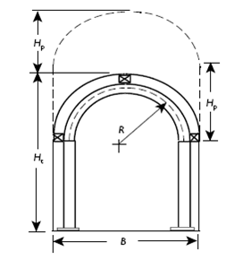
Consider a pin-connected, two-segment, semi-circular steel rib shown in the sketch.(a) If the bearing ends are free to rotate, find the thrust and moment in the steel. Data are: Hp = 10 ft, Ht=18 ft, B = 16 ft, R = 7.5 ft, set spacing S = 6 ft and specific weight of rock γ =
Two-piece continuous steel sets are to support a tunnel with a semi-circular roof having a radius of 12 ft and a straight leg section of 13 ft. The tunnel is therefore 24 ft wide by 25 ft high. The crown is assumed hinged and the ends of the steel arch are fixed. For preliminary design assume 1 in.
Two-piece continuous steel sets are to support a tunnel with a semi-circular roof having a radius of 12 ft and a straight leg section of 13 ft. The tunnel is therefore 24 ft wide by 25 ft high. The crown is assumed hinged and the ends of the steel arch are fixed. For preliminary design assume 1 in.
Two-piece continuous steel sets are to support a tunnel with a semi-circular roof having a radius of 3.5 m, and a straight leg section of 4 m. The tunnel is therefore 7 m wide by 7.5 m high. The crown is assumed hinged and the ends of the steel arch are fixed. For preliminary design assume 2.5 cm
Consider the analysis of tunnel bolting leading to the equation If bolting is on a square pattern of spacing S and a 45? cone of influence is assigned to the bolt forces, show that this equation is equivalent to that of Bischoff and Smart (1977), equation 8, where provided a Mohr-Coulomb yield
Layout an equivalent bolting pattern for the crown portion of the tunnel in Problem 8 using 1 inch diameter rebar tensioned to 60,000 psi, specify bolt spacing and length.
Yieldable steel arches are used to control squeezing ground in a tunnel where the rock pressure corresponds to a rock “head” of 15 ft. Estimate the steel area needed for this situation. What proportion of the area is needed for bending stress?
Layout an equivalent bolting pattern for the crown portion of the tunnel in Problem 10 using 2.5 cm diameter rebar tensioned to 410 MPa. Specify bolt spacing and length.
Yieldable steel arches are used to control squeezing ground in a tunnel where the rock pressure corresponds to a rock “head” of 4.6 m. Estimate the steel area needed for this situation. What proportion of the area is needed for bending stress?
An arched tunnel is driven in moderately blocky and seamy, wet ground at a depth of 1,970 ft. The tunnel is 14 ft wide by 11 ft high; the back arch is semi-circular.(a) Specify a suitable steel set size (web depth, flange width, weight per foot), set spacing, and maximum blocking point spacing for
For Problem 4.16 conditions, find an equivalent bolting pattern (bolt diameter, strength, length, and spacing), that provides the same approximate thrust capacity.
For the same “rock pressure” and semi-circular arch in Problem 16, determine the cross-sectional area of yieldable steel arches for ground control.
An arched tunnel is driven in moderately blocky and seamy, wet ground at a depth of 600 m. The tunnel is 4.3 m wide by 3.4 m high; the back arch is semi-circular.(a) Specify a suitable steel set size (web depth, flange width, weight per foot), set spacing and maximum blocking point spacing for
For Problem 19 conditions, find an equivalent bolting pattern (bolt diameter, strength, length, and spacing), that provides the same approximate thrust capacity.
For the same “rock pressure” and semi-circular arch in Problem 19, determine the cross-sectional area of yieldable steel arches for ground control.
An arched tunnel is driven in moderately blocky and seamy, wet ground at a depth of 970 ft. The tunnel is 18 ft wide by 21 ft high; the back arch is semi-circular.(a) Specify a suitable steel set size (web depth, flange width, weight per foot), set spacing and maximum blocking point spacing for
For the same “rock pressure” and semi-circular arch in Problem 4.22, determine the cross-sectional area of yieldable steel arches for ground control.
For Problem 22 conditions, find an equivalent bolting pattern (bolt diameter, strength, length, and spacing), that provides the same approximate thrust capacity.
An arched tunnel is driven in moderately blocky and seamy, wet ground at a depth of 297 m. The tunnel is 5.51 m wide by 61.4 m high; the back arch is semi-circular.(a) Specify a suitable steel set size (web depth, flange width, weight per foot), set spacing and maximum blocking point spacing for
For the same “rock pressure” and semi-circular arch in Problem 25, determine the cross-sectional area of yieldable steel arches for ground control.
For Problem 4.26 conditions, find an equivalent bolting pattern (bolt diameter, strength, length, and spacing), that provides the same thrust capacity.
Semi-circular yieldable steel arches with a nominal radius of 6.75 ft are used in main entries to a coal mine developed from outcrop under plateau overburden. Seam depth at a point of interest is 2,350 ft where ground pressure on the supports is estimated to be 20 psi. Determine cross-sectional
With reference to Problem 28, an alternative support system in the form of fixed steel sets is considered with entry height 11.75 ft. Select a suitable steel rib for this alternative specifying steel weight and size, set spacing and maximum blocking point spacing.
With reference to Problem 29, develop an approximately equivalent bolting reinforcement system using one-inch diameter, Grade 60 steel (60,000 psi elastic limit) bolts. Rock properties are: E = 4.9 million psi, v = 0.18, Co = 7,500 psi, To = 750psi,γ = 148pcf. Specify bolt spacing’s (in-row,
Semi-circular yieldable steel arches with a nominal radius of 2 m are used in main entries to a coal mine developed from outcrop under plateau overburden. Seam depth at a point of interest is 716 m where ground pressure on the supports is estimated to be 138 kPa. Determine cross-sectional area
With reference to Problem 31, an alternative support system in the form of fixed steel sets is considered with entry height 3.6 m. Select a suitable steel rib for this alternative specifying steel weight and size, set spacing, and maximum blocking point spacing.
With reference to Problem 4.32, develop an approximately equivalent bolting reinforcement system using one-inch diameter, Grade 60 steel (410 MPa elastic limit) bolts. Rock properties are: E =33.8GPa, v = 0.18, Co = 51.7 MPa, To = 5.17Mpa, γ = 23.4kN/m3. Specify bolt spacing’s (in-row, between
An arched tunnel is driven in moderately blocky and seamy, wet ground at a depth of 2,830 ft where rock properties are: Co = 14,300 psi, To = 1,430 psi, E = 4.25 (106) psi, G = 1.8 (106) psi, γ = 156pcf. The tunnel is 14 ft wide by 17 ft high; the back arch is semi-circular. Specify a suitable
With reference to Problem 4.34, specify support in the form of rock reinforcement by bolting on a square pattern that has the same support capacity (bolt diameter, spacing, length, steel strength).
With reference to Problem 7, specify support in the form of yieldable steel arches that support the same “rock pressure” (steel area, set spacing, steel strength).
An arched tunnel is driven in moderately blocky and seamy, wet ground at a depth of 863 m where rock properties are, Co = 98.6 MPa, To = 9.86 MPa, E = 29.3GPa, G = 12.4GPa, γ = 24.7kN/m3. The tunnel is 4.3 m wide by 5.2 m high; the back arch is semi-circular. Specify a suitable steel set size (web
With reference to Problem 4.37, specify support in the form of rock reinforcement by bolting on a square pattern that has the same support capacity (bolt diameter, spacing, length, steel strength).
With reference to Problem 37, specify support in the form of yieldable steel arches that support the same “rock pressure” (steel area, set spacing, steel strength).
An arched (semi-circle) rectangular tunnel 28 ft wide and 28 ft high is driven in dry, moderately blocky, and seamy ground.(a) Select a steel rib suitable for these conditions; specify flange width, web depth, weight per foot, and set spacing.(b) Suppose yieldable steel arches where used to support
An arched (semi-circle) rectangular tunnel 8.5 m wide and 8.5 m high is driven in dry, moderately blocky, and seamy ground.(a) Select a steel rib suitable for these conditions; specify flange width, web depth, weight per foot, and set spacing.(b) Suppose yieldable steel arches where used to support
Explain the objective of rock mass classification schemes, RMR and Q, why RQD is important to such schemes, what the main components are and what the main differences are. Organize your comparisons and contrasts in itemized lists. In a run of 5 ft of NQ core (1.875 in. diameter), fractures are
Explain the objective of rock mass classification schemes, RMR and Q, why RQD is important to such schemes, what the main components are and what the main differences are. In a run of 1.5 m of NQ core (4.75 cm diameter), fractures are observed at 8.4, 18.3, 33.5, 39.9, 66.8, 77.0, 90.7, 95.5,
Showing 100 - 200
of 335
1
2
3
4
Step by Step Answers