New Semester
Started
Get
50% OFF
Study Help!
--h --m --s
Claim Now
Question Answers
Textbooks
Find textbooks, questions and answers
Oops, something went wrong!
Change your search query and then try again
S
Books
FREE
Study Help
Expert Questions
Accounting
General Management
Mathematics
Finance
Organizational Behaviour
Law
Physics
Operating System
Management Leadership
Sociology
Programming
Marketing
Database
Computer Network
Economics
Textbooks Solutions
Accounting
Managerial Accounting
Management Leadership
Cost Accounting
Statistics
Business Law
Corporate Finance
Finance
Economics
Auditing
Tutors
Online Tutors
Find a Tutor
Hire a Tutor
Become a Tutor
AI Tutor
AI Study Planner
NEW
Sell Books
Search
Search
Sign In
Register
study help
engineering
civil engineering
Engineering Mechanics Statics 11 Edition Russell C. Hibbeler - Solutions
Two couples act on the frame. Determine the resultant couple moment. Compute the result by resolving each force into x and y components and(a) Finding the moment of each couple (Eq. 4 -13) and(b) Summing the moments of all the force components about point B.Given:F1 = 80 lb d = 4ftF2 = 50 lb e = 3
Determine the couple moment. Express the result as a Cartesian vector. Determine the couple moment. Express the result as a Cartesian vector.Given:F = (8 -4 10)) Na = 5 mb = 3 mc = 4 md = 2 me = 3 m
Determine the couple moment. Express the result as a Cartesian vector.Given:F = 80 Na = 6 mb = 10 mc = 10 md = 5 me = 4 mf = 4 m
If the resultant couple of the two couples acting on the fire hydrant is MR = {−15i + 30j} N ∙ m, determine the force magnitude P.Given:a = 0.2 mb = 0.150 mM = (-15 30 0) N ∙ mF = 75 N
If the resultant couple of the three couples acting on the triangular block is to be zero, determine the magnitude of forces F and P.Given:F1 = 150 Na = 300 mmb = 400 mmd = 600 mm
Determine the couple moment that acts on the assembly. Express the result as a Cartesian vector. Member BA lies in the x-y plane.Given:F = (0 0 100) Na = 300 mmb = 150 mmc = 200 mmd = 200 mmθ = 60 deg
If the magnitude of the resultant couple moment is M, determine the magnitude F of the forces applied to the wrenches.Given:M = 15 N ∙ mc = 200 mma = 300 mm d = 200 mmb = 150 mm θ = 60 deg
The gears are subjected to the couple moments shown. Determine the magnitude and coordinate direction angles of the resultant couple moment.Given:M1 = 40 lb⋅ ftM2 = 30 lb⋅ ftθ1 = 20 degθ2 = 15 degθ3 = 30 deg
Express the moment of the couple acting on the rod in Cartesian vector form. What is the magnitude of the couple moment?Given:a = 1.5 mb = 0.5 mc = 0.5 md = 0.8 m
Express the moment of the couple acting on the pipe assembly in Cartesian vector form. Solve the problem(a) Using Eq. 4-13,(b) Summing the moment of each force about point O.Given:a = 0.3 mb = 0.4 mc = 0.6 mF = (- 6 2 3) N
A couple acts on each of the handles of the minidual valve. Determine the magnitude and coordinate direction angles of the resultant couple moment.Given:F1 = 35 N θ = 60 degF2 = 25 Nr1 = 175 mmr2 = 175 mm
Express the moment of the couple acting on the pipe in Cartesian vector form. What is the magnitude of the couple moment?Given:F = 125 Na = 150 mmb = 150 mmc = 200 mmd = 600 mm
If the couple moment acting on the pipe has a magnitude M, determine the magnitude F of the forces applied to the wrenches.Given:M 300 = N ∙ ma = 150 mmb = 150 mmc = 200 mmd = 600 mm
Replace the force at A by an equivalent force and couple moment at point O.Given:F = 375 Na = 2 mb = 4 mc = 2 md = 1 mθ = 30 deg
Replace the force at A by an equivalent force and couple moment at point P.Given:F = 375 Na = 2 mb = 4 mc = 2 md = 1 mθ = 30 deg
Replace the force system by an equivalent resultant force and couple moment at point O.Given:F1 = 60 lb a = 2 ftF2 = 85 lb b = 3 ftF3 = 25 lb c = 6 ftθ = 45 deg d = 4 fte = 3f = 4
Replace the force system by an equivalent resultant force and couple moment at point P.Given:F1 = 60 lb a = 2 ftF2 = 85 lb b = 3 ftF3 = 25 lb c = 6 ftθ = 45 deg d = 4 fte = 3 f = 4
Replace the force system by an equivalent force and couple moment at point O.Units Used:kip = 103 lbGiven:F1 = 430 lb F2 = 260 lba = 2 ft e = 5 ft= 8 ft f = 12c = 3 ft g = 5d =a θ = 60 deg
Replace the force system by an equivalent force and couple moment at point P.Units Used:kip = 103 lbGiven:F1 = 430 lb F2 = 260 lba = 2 ft e = 5 ftb = 8 ft f = 12c = 3 ft g = 5d =a θ = 60 deg
Replace the loading system acting on the post by an equivalent resultant force and couple moment at point O.Given:F1 = 30 lb a = 1 ft d = 3F2 = 40 lb b = 3 ft e = 4F3 = 60 lb c = 2 ft
Replace the loading system acting on the post by an equivalent resultant force and couple moment at point P.Given:F1 = 30 lbF2 = 40 lbF3 = 60 lba = 1 ftb = 3 ftc = 2 ftd = 3e = 4
Replace the force and couple system by an equivalent force and couple moment at point O.Units Used:kN = 103 NGiven:M = 8kNm θ = 60 dega = 3 m f = 12b = 3 m g = 5c = 4 m F1 = 6kNd = 4m F2 = 4kNe = 5 m
Replace the force and couple system by an equivalent force and couple moment at point P.Units Used:kN = 103 NGiven:M 8kN = ⋅m θ = 60 dega = 3 m f = 12b = 3 m g = 5c = 4 m F1 = 6kNd = 4 m F2 = 4kNe = 5 m
Replace the force system by a single force resultant and specify its point of application, measured along the x axis from point O.Given:F1 = 125 lbF2 = 350 lbF3 = 850 lba = 2 ftb = 6 ftc = 3 ftd = 4 ft
Replace the force system by a single force resultant and specify its point of application, measured along the x axis from point P.Given:F1 = 125 lb a = 2 ftF2 = 350 lb b = 6 ftF3 = 850 lb c = 3 ftd = 4 ft
The forces and couple moments which are exerted on the toe and heel plates of a snow ski are Ft, Mt, and Fh, Mh, respectively. Replace this system by an equivalent force and couple moment acting at point O. Express the results in Cartesian vector form.Given:a = 120 mmb = 800 mm
The forces and couple moments which are exerted on the toe and heel plates of a snow ski are Ft, Mt, and Fh, Mh, respectively. Replace this system by an equivalent force and couple moment acting at point P. Express the results in Cartesian vector form.Given:a = 120 mmb = 800 mmFt = (-50 80 -158)
Replace the three forces acting on the shaft by a single resultant force. Specify where the force acts, measured from end B.Given:F1 = 500 lbF2 = 200 lbF3 = 260 lba = 5 ft e = 3b = 3 ft f = 4c = 2 ft g = 12d = 4 ft h = 5
Replace the three forces acting on the shaft by a single resultant force. Specify where the force acts, measured from end B.Given:F1 = 500 lbF2 = 200 lbF3 = 260 lba = 5 ft e = 3b = 3 ft f = 4c = 2 ft g = 12d = 4 ft h = 5
Replace the loading on the frame by a single resultant force. Specify where its line of action intersects member AB, measured from A.Given:F1 = 300 lb M = 600 lb⋅ ftF2 = 200 lb a = 3 ftb = 4 ftF3 = 400 lbc = 2 ftF4 = 200 lb d = 7 ft
Replace the loading on the frame by a single resultant force. Specify where the force acts, measured from end A.Given:F1 = 450 N a = 2 mF2 = 300 N b = 4 mF3 = 700 N c = 3 mθ = 60 deg M = 1500 N ∙ mφ = 30 deg
Replace the loading on the frame by a single resultant force. Specify where the force acts , measured from end B.Given:F1 = 450 N a = 2 mF2 = 300 N b = 4 mF3 = 700 N c = 3 mθ = 60 deg M = 1500 N ∙ mφ = 30deg
Replace the loading system acting on the beam by an equivalent resultant force and couple moment at point O.Given:F1 = 200 NF2 = 450 NM = 200N ∙ ma = 0.2 mb = 1.5 mc = 2 md = 1.5 mθ = 30 deg
Determine the magnitude and direction θ of force F and its placement d on the beam so that the loading system is equivalent to a resultant force FR acting vertically downward at point A and a clockwise couple moment M.Units Used:kN = 103 NGiven:F1 = 5kN a = 3 mF2 = 3kN b = 4 mFR = 12kN c = 6
Determine the magnitude and direction θ of force F and its placement d on the beam so that the loading system is equivalent to a resultant force FR acting vertically downward at point A and a clockwise couple moment M.Units Used:kN = 103 NGiven:F1 = 5kN a = 3 mF2 = 3kN b = 4 mFR = 10kN c = 6
Replace the loading on the frame by a single resultant force. Specify where its line of action intersects member AB, measured from A.Given:F1 = 500 N a = 3 mF2 = 300 N b = 2 mc = 1 mF3 = 250 Nd = 2 mM = 400 N ∙ m e = 3 mθ = 60 deg f = 3g = 4
Replace the loading on the frame by a single resultant force. Specify where its line of action intersects member CD, measured from end C.Given:F1 = 500 N a = 3 mF2 = 300 N b = 2 mc = 1 mF3 = 250 Nd = 2 mM = 400 N ∙ m e = 3 mθ = 60 deg f = 3g = 4
Replace the force system acting on the frame by an equivalent resultant force and specify where the resultant's line of action intersects member AB, measured from point A.Given:F1 = 35 lb a = 2 ftF2 = 20 lb b = 4 ftF3 = 25 lb c = 3 ftθ = 30 deg d = 2 ft
Replace the force system acting on the frame by an equivalent resultant force and specify where the resultant's line of action intersects member BC, measured from point B.Given:F1 = 35 lbF2 = 20 lbF3 = 25 lbθ = 30 dega = 2 ftb = 4 ftc = 3 ftd = 2 ft
Replace the force system acting on the frame by an equivalent resultant force and couple moment acting at point A.Given:F1 = 35 lb a = 2 ftF2 = 20 lb b = 4 ftF3 = 25 lb c = 3 ftθ = 30 deg d = 2 ft
Replace the force and couple-moment system by an equivalent resultant force and couple moment at point O. Express the results in Cartesian vector form.Units Used:kN = 103 N
Replace the force and couple-moment system by an equivalent resultant force and couple moment at point O. Express the results in Cartesian vector form.Units Used:kN = 103 NGiven:F = (8 6 8) kNM = (-20 -70 20) kN ∙ ma = 3 mb = 3 m e = 5 mc = 4 m f = 6 md = 6 m g = 5 m
Replace the force and couple-moment system by an equivalent resultant force and couple moment at point Q. Express the results in Cartesian vector form.Units Used:kN = 103 NGiven:F = (8 6 8) kNM = (-20 -70 20) k N ∙ ma = 3 mb = 3 m e = 5 mc = 4 m f = 6 md = 6 m g = 5 m
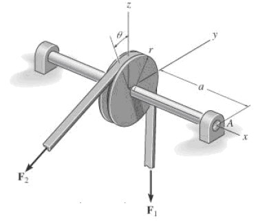
The belt passing over the pulley is subjected to forces F1 and F2. F1 acts in the k direction. Replace these forces by an equivalent force and couple moment at point A. Express the result in Cartesian vector form. Given: F1 = 40 N r = 80 mm F2 = 40 N a = 300 mm ? = 0 deg
The belt passing over the pulley is subjected to forces F1 and F2. F1 acts in the −k direction. Replace these forces by an equivalent force and couple moment at point A. Express the result in Cartesian vector form.Given:F1 = 40 NF2 = 40 Nθ = 0 degr = 80 mma = 300 mmθ = 45 deg
Replace this system by an equivalent resultant force and couple moment acting at O. Express the results in Cartesian vector form.Given:F1 = 50 NF2 = 80 NF3 = 180 Na = 1.25 mb = 0.5 mc = 0.75 m
Handle forces F1 and F2 are applied to the electric drill. Replace this system by an equivalent resultant force and couple moment acting at point O. Express the results in Cartesian vector form.Given:a = 0.15 mb = 0.25 mc = 0.3 mF1 = (6 -3 -10) NF2 = (0 2 -4) N
A biomechanical model of the lumbar region of the human trunk is shown. The forces acting in the four muscle groups consist of FR for the rectus, FO for the oblique, FL for the lumbar latissimus dorsi, and FE for the erector spinae. These loadings are symmetric with respect to the y - z plane.
The building slab is subjected to four parallel column loadings. Determine the equivalent resultant force and specify its location (x, y) on the slab.Units Used:kN = 103 NGiven:F1 = 30 kN a = 3 mF2 = 40 kN b = 8 mF3 = 20 kN c = 2 mF4 = 50 kN d = 6 me = 4 m
The building slab is subjected to four parallel column loadings. Determine the equivalent resultant force and specify its location (x, y) on the slab.Units Used:kN = 103 NGiven:F1 = 20 kN a = 3 mF2 = 50 kN b = 8 mF3 = 20 kN c = 2 mF4 = 50 kN d = 6 me = 4 m
The pipe assembly is subjected to the action of a wrench at B and a couple at A. Determine the magnitude F of the couple forces so that the system can be simplified to a wrench acting at point C.Given:a = 0.6 mb = 0.8 mc = 0.25 md = 0.7 me = 0.3 mf = 0.3 mg = 0.5 mh = 0.25 mP = 60 NQ = 40 N
The three forces acting on the block each have a magnitude F1 = F2 = F3. Replace this system by a wrench and specify the point where the wrench intersects the z axis, measured from point O.Given:F1 = 10 lb a = 6 ftF2 = F1 b = 6 ftF3 = F1 c = 2 ft
Replace the three forces acting on the plate by a wrench. Specify the magnitude of the force and couple moment for the wrench and the point P(x, y) where its line of action intersects the plate.Units Used:kN = 103NGiven:FA = 500 NFB = 800 NFC = 300 Na = 4 mb = 6 m
Replace the three forces acting on the plate by a wrench. Specify the magnitude of the force and couple moment for the wrench and the point P(y, z) where its line of action intersects the plate.Given:FA = 80 lb a = 12 ftFB = 60 lb b = 12 ftFC = 40 lb
The loading on the bookshelf is distributed as shown. Determine the magnitude of the equivalent resultant location, measured from point O.Given:w1 = 2lb/ftw2 = 3.5lb/fta = 2.75 ftb = 4 ftc = 1.5 ft
Replace the loading by an equivalent resultant force and couple moment acting at point A.Units Used:kN = 103 NGiven:w1 600N/mw2 = 600 N/ma = 2.5 mb = 2.5 m
Replace the loading by an equivalent force and couple moment acting at point O.Units Used:kN = 103 NGiven:w = 6 kN/mF = 15 kNM = 500 kN ∙ ma = 7.5 mb = 4.5 m
Replace the loading by a single resultant force, and specify the location of the force on the beam measured from point O. Units Used: kN = 103 N Given: w = 6 kN/m F = 15 kN M = 500 kN ∙ m a = 7.5 m b = 4.5 m
The column is used to support the floor which exerts a force P on the top of the column.The effect of soil pressure along its side is distributed as shown. Replace this loading by an equivalent resultant force and specify where it acts along the column, measured from its base A.Units Used: kip =
Replace the loading by an equivalent resultant force and specify its location on the beam, measured from point B.Units Used:kip = 103 lbGiven:w1 = 800lb/ftw2 = 500lb/fta = 12 ftb = 9 ft
Replace the distributed loading by an equivalent resultant force, and specify its location on the beam, measured from the pin at C.Units Used:kip = 103 lbGiven:w = 800 lb/fta = 15 ftb = 15 ftθ = 30 deg
The beam supports the distributed load caused by the sandbags. Determine the resultant force on the beam and specify its location measured from point A.Units Used: kN = 103 NGiven:w1 = 1.5 kN/m a = 3 mw2 = 1kN/m b = 3 mw3 = 2.5kN/m c = 1.5 m
Determine the length b of the triangular load and its position a on the beam such that the equivalent resultant force is zero and the resultant couple moment is M clockwise.Units Used:kN = 103 NGiven:w1 = 4kN/m w2 = 2.5 kN/mM = 8 kN ∙ m c = 9 m
Replace the distributed loading by an equivalent resultant force and specify its location, measured from point A.Units Used:kN = 103NGiven:w1 = 800N/mw2 = 200N/ma = 2 mb = 3 m
The distribution of soil loading on the bottom of a building slab is shown. Replace this loading by an equivalent resultant force and specify its location, measured from point O.Units Used:kip = 103lbGiven:w1 = 50 lb/ftw2 = 300 lb/ftw3 = 100 lb/fta = 12 ftb = 9 ft
The beam is subjected to the distributed loading. Determine the length b of the uniform load and its position a on the beam such that the resultant force and couple moment acting on the beam are zero.Given:w1 = 40lb/ft c = 10ftw2 = 60lb/ft = 6 ft
Replace the loading by an equivalent resultant force and specify its location on the beam, measured from point B.Units Used:kip = 103 lbGiven:w1 = 800lb/ftw2 = 500lb/fta = 12 ftb = 9 ft
Replace the distributed loading by an equivalent resultant force and specify where its line of action intersects member AB, measured from A.Given:w1 = 200N/mw2 = 100N/mw3 = 200N/ma = 5 mb = 6 m
Replace the distributed loading by an equivalent resultant force and specify where its line of action intersects member BC, measured from C.Units Used:kN = 103NGiven:w1 = 200N/mw2 = 100N/mw3 = 200N/ma = 5 mb = 6 m
Replace the loading by an equivalent resultant force and couple moment acting at point O.Units Used:kN = 103 NGiven:w1 = 7.5kN/mw2 = 20kN/ma = 3 mb = 3 mc = 4.5 m
Determine the equivalent resultant force and couple moment at point O.Units Used:kN = 103 NGiven:a = 3 mwO = 3kN/mw(x) = wO(x/a)2
Wind has blown sand over a platform such that the intensity of the load can be approximated by the function w = w0(x/d) 3, simplify this distributed loading to an equivalent resultant force and specify the magnitude and location of the force, measured from A.Units Used:kN = 103NGiven:w0 = 500N/md =
Determine the equivalent resultant force and its location, measured from point O.
Determine the equivalent resultant force acting on the bottom of the wing due to air pressure and specify where it acts, measured from point A.Given:a = 3 ftk = 86lb/ft3w(x) = kx2
Currently eighty-five percent of all neck injuries are caused by rear-ends car collisions. To alleviate this problem, an automobile seat restraint has been developed that provides additional pressure contact with the cranium. During dynamic tests the distribution of load on the cranium has been
Determine the equivalent resultant force of the distributed loading and its location, measured from point A. Evaluate the integrals using Simpson's rule.Units Used:kN = 103 NGiven:c1 = 5c2 = 16a = 3b = 1
Determine the coordinate direction angles of F, which is applied to the end A of the pipe assembly, so that the moment of F about O is zero.Given:F = 20 lba = 8 inb = 6 inc = 6 ind = 10 in
Determine the moment of the force F about point O. The force has coordinate direction angles α, β, γ. Express the result as a Cartesian vector.Given:F = 20 lb a = 8 inα = 60 deg b = 6 inβ = 120 deg c = 6 inγ = 45 deg d = 10 in
Replace the force at A by an equivalent resultant force and couple moment at point P. Express the results in Cartesian vector form.Units Used:kN = 103 NGiven:a = 4 mb = 6 mc = 8 md = 4 mF = (-300 200 -500) N
Determine the moment of the force FC about the door hinge at A. Express the result as a Cartesian vector.Given:F = 250 Nb = 1 mc = 2.5 md = 1.5 me = 0.5 mθ = 30 deg
Determine the magnitude of the moment of the force FC about the hinged axis aa of the door.Given:F = 250 Nb = 1 mc = 2.5 md = 1.5 me = 0.5 mθ = 30 deg
A force F1 acts vertically downward on the Z-bracket. Determine the moment of this force about the bolt axis (z axis), which is directed at angle θ from the vertical.Given:F1 = 80 Na = 100 mmb = 300 mmc = 200 mmθ = 15 deg
Replace the force F having acting at point A by an equivalent force and couple moment at point C.Units Used: kip = 103 lbGiven:F = 50 lba = 10 ftb = 20 ftc = 15 ftd = 10 fte = 30 ft
The horizontal force F acts on the handle of the wrench. What is the magnitude of the moment of this force about the z axis?Given:F = 30 Na = 50 mmb = 200 mmc = 10 mmθ = 45 deg
The horizontal force F acts on the handle of the wrench. Determine the moment of this force about point O. Specify the coordinate direction angles α, β, γ of the moment axis.Given:F = 30 N c = 10 mma = 50 mm θ = 45 degb = 200 mm
Draw the free-body diagram of the sphere of weight W resting between the smooth inclined planes. Explain the significance of each force on the diagram.Given:W = 10 lbθ1 = 105 degθ2 = 45 deg
Draw the free-body diagram of the hand punch, which is pinned at A and bears down on the smooth surface at B.Given:F = 8 lba = 1.5 ftb = 0.2 ftc = 2 ft
If the resultant couple moment of the three couples acting on the triangular block is to be zero, determine the magnitudes of forces F and P.Given:F1 = 10 lba = 3 inb = 4 inc = 6 ind = 3 inθ = 30 deg
Draw the free-body diagram of the beam supported at A by a fixed support and at B by a roller.Explain the significance of each force on the diagram.Given:w = 40lb/fta = 3 ftb = 4 ftθ = 30 deg
Draw the free-body diagram of the jib crane AB, which is pin-connected at A and supported by member (link) BC.Units Used:kN = 103 NGiven:F = 8kNa = 3 mb = 4 mc = 0.4 md = 3e = 4
Draw the free-body diagram of the C-bracket supported at A, B, and C by rollers. Explain the significance of each force on the diagram.Given:a = 3 ftb = 4 ftθ1 = 30 degθ2 = 20 degF = 200 lb
Draw the free-body diagram of the smooth rod of mass M which rests inside the glass. Explain the significance of each force on the diagram.Given:M = 20 gma = 75 mmb = 200 mmθ = 40 deg
Draw the free-body diagram of the €œspanner wrench€ subjected to the force F. The support atA can be considered a pin, and the surface of contact at B is smooth. Explain the significance of each force on the diagram.Given:F = 20 lba = 1 inb = 6 in
Draw the free-body diagram of the automobile, which is being towed at constant velocity up the incline using the cable at C. The automobile has a mass M and center of mass at G. The tires are free to roll. Explain the significance of each force on the diagram.Units Used:Mg = 103 kgGiven:M = 5 Mg d
Draw the free-body diagram of the uniform bar, which has mass M and center of mass at G. The supports A, B, and C are smooth.Given:M = 100 kga = 1.75 mb = 1.25 mc = 0.5 md = 0.2 mg = 9.81m/s2
The sphere of weight W rests between the smooth inclined planes. Determine the reactions at the supports.Given:W = 10 lbθ1 = 105 degθ2 = 45 deg
Draw the free-body diagram of the beam, which is pin-connected at A and rocker-supported at B.Given:F = 500 NM = 800 N ∙ ma = 8 mb = 4 mc = 5 m
Determine the magnitude of the resultant force acting at pin A of the hand punch.Given:F = 8 lba = 1.5 ftb = 0.2 ftc = 2 ft
The C-bracket is supported at A, B, and C by rollers. Determine the reactions at the supports.Given:a = 3 ftb = 4 ftθ1 = 30 degθ2 = 20 degF = 200 lb
The smooth rod of mass M rests inside the glass. Determine the reactions on the rod.Given:M = 20 gma = 75 mmb = 200 mmθ = 40 degg = 9.81m/s2
Showing 300 - 400
of 2574
1
2
3
4
5
6
7
8
9
10
11
12
13
14
15
Last
Step by Step Answers
.PNG)
.PNG)
.PNG)
.PNG)
.PNG)
.PNG)
.PNG)
.PNG)
.PNG)
.PNG)
.PNG)
.PNG)
.PNG)
.PNG)
.PNG)
.PNG)
.PNG)
.PNG)
.PNG)
.PNG)
.PNG)
.PNG)
.PNG)
.PNG)
.PNG)
.PNG)
.PNG)
.PNG)
.PNG)
.PNG)
.PNG)
.PNG)
.PNG)
.PNG)
.PNG)
.PNG)
.PNG)
.PNG)
.PNG)
.PNG)
.PNG)
.PNG)
.PNG)
.PNG)
.PNG)
.PNG)
.PNG)
.PNG)
.PNG)
.PNG)
.PNG)
.PNG)
.PNG)
.PNG)
.PNG)
.PNG)
.PNG)
.PNG)
.PNG)
.PNG)
.PNG)
.PNG)
.PNG)
.PNG)
.PNG)
.PNG)
.PNG)
.PNG)
.PNG)
.PNG)
.PNG)
.PNG)
.PNG)
.PNG)
.PNG)
.PNG)
.PNG)
.PNG)
.PNG)
.PNG)
.PNG)
.PNG)
.PNG)
.PNG)
.PNG)
.PNG)
.PNG)
.PNG)
.PNG)
.PNG)
.PNG)
.PNG)
.PNG)
.PNG)
.PNG)

