

Question: (a) For the circuit of Problem 5.1, sketch load lines in the I c - V ce plane for R L = 2 k¦ and
(a) For the circuit of Problem 5.1, sketch load lines in the Ic- Vceplane for RL= 2 k„¦ and RL= 10 k„¦.
(b) Calculate the maximum average sinusoidal output power that can be delivered to RL (both values) before clipping occurs in (a) above. Sketch corresponding waveforms for Ic1, Vce1, and Pc1.
(c) Calculate the circuit efficiency for each value of RL in (b). (Neglect power dissipated inQ3 and R3.)
(d) Select RL for maximum efficiency in this circuit and calculate the corresponding average output power with sinusoidal signals.
Problem 5.1
A circuit as shown in Fig. 5.1 has VCC = 15V, R1 = R2 = 0, R3 = 5k„¦, RL = 2k„¦, VCE(sat) = 0.2 V, and VBE(on) = 0.7 V. All device areas are equal.
Figure 5.1
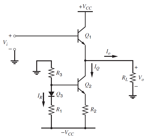
+Vc_ Q1 V; I'e RL R3 Q2 Q3 R2 R1 -Vcc
Step by Step Solution
3.45 Rating (158 Votes )
There are 3 Steps involved in it
a b 286 mA P L I max 572 286 mW 82 mW 148 V I ... View full answer

Get step-by-step solutions from verified subject matter experts
Document Format (2 attachments)
1528_605d88e1b0d97_686854.pdf
180 KBs PDF File
1528_605d88e1b0d97_686854.docx
120 KBs Word File