

Question: A circuit as shown in Fig. 5.1 has V CC = 15V, R 1 = R 2 = 0, R 3 = 5k¦, R L
A circuit as shown in Fig. 5.1 has VCC= 15V, R1= R2= 0, R3= 5k„¦, RL= 2k„¦, VCE(sat)= 0.2 V, and VBE(on)= 0.7 V. All device areas are equal.
(a). Sketch the transfer characteristic from Vi to Vo.
(b). Repeat (a) if RL = 10 k„¦.
(c). Sketch the waveform of Vo if a sinusoidal input voltage with an amplitude (zero to peak) of 10 V is applied at Vi in (a) and (b) above.
(d). Use SPICE to verify (a), (b), and (c) and also to determine second and third harmonic distortion in Vo for the conditions in (c).
Figure 5.1
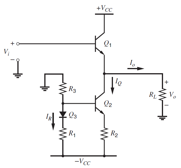
+Vc_ Q1 V; I'e RL R3 Q2 Q3 R2 R1 -Vcc
Step by Step Solution
3.47 Rating (167 Votes )
There are 3 Steps involved in it
a Thus I Q 286 mA I Q R L 286 ... View full answer

Get step-by-step solutions from verified subject matter experts
Document Format (2 attachments)
1528_605d88e1b0beb_686853.pdf
180 KBs PDF File
1528_605d88e1b0beb_686853.docx
120 KBs Word File