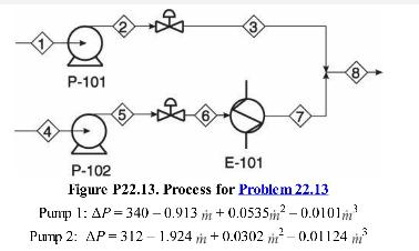
Consider the situation illustrated in Figure P22.13. Due to downstream considerations, (P_{8}) is always maintained at (200
Question:
Consider the situation illustrated in Figure P22.13. Due to downstream considerations, \(P_{8}\) is always maintained at \(200 \mathrm{kPa}\). It is known that \(P_{1}=100 \mathrm{kPa}\) and \(P_{4}=100 \mathrm{kPa}\), and because the feeds come from storage tanks maintained at constant pressure, they are always constant. It is also known that \(P_{3}=225 \mathrm{kPa}, P_{5}=375 \mathrm{kPa}, P_{6}=250 \mathrm{kPa}, P_{7}=225 \mathrm{kPa}\), and \(\dot{m}_{1}=15,500 \mathrm{~kg} / \mathrm{h}\). The pump curves are given by the following equations, with \(\Delta P\) in \(\mathrm{kPa}\) and \(\dot{m}\) in \(\mathrm{Mg} / \mathrm{h}\) :
Figure 22.13

a. Calculate \(\dot{m}_{4}\) and \(\Delta P_{23}\) for this situation.
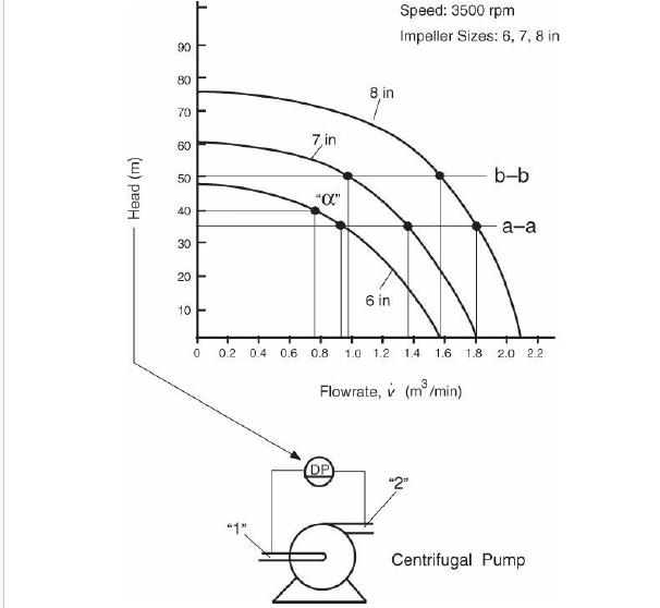
b. Sketch the pump and system curves for this situation as illustrated in Section 21. 2.1. Identify the pressure drop across the valves on the sketch.
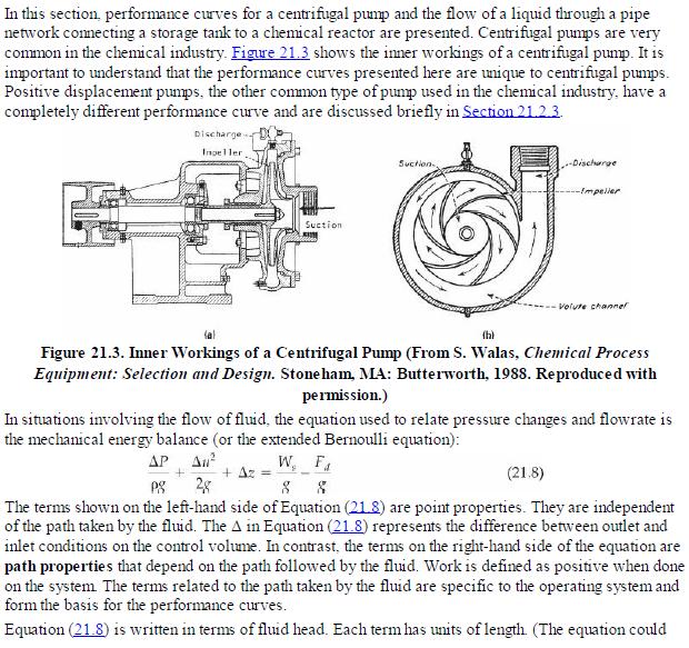
Data from section 21.21


Step by Step Answer:

Analysis Synthesis And Design Of Chemical Processes
ISBN: 9780132618120
4th Edition
Authors: Richard Turton, Richard C. Bailie, Wallace B. Whiting, Joseph A. Shaeiwitz, Debangsu Bhattacharyya


