

Question: A piping system takes water at $60^{circ} mathrm{F}$ from a tank at atmospheric pressure to a plant vessel at 25 psig that is $30 mathrm{ft}$
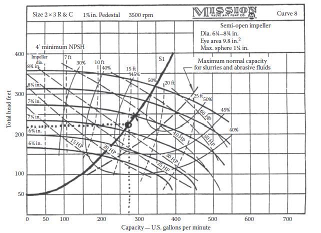
A piping system takes water at $60^{\circ} \mathrm{F}$ from a tank at atmospheric pressure to a plant vessel at 25 psig that is $30 \mathrm{ft}$ higher than the upstream tank. The transfer line contains $300 \mathrm{ft}$ of $3 \mathrm{in}$. sch 40 pipe, $1090^{\circ}$ elbows, an orifice meter, a $2 \times 3$ pump with a $73 / 4$ in. impeller (with the characteristic as given on Figure 8.2), and a $3 \times 2$ equal percentage control valve. A constant flow rate of $200 \mathrm{gpm}$ is required in the system.
Figure 8.2
(a) What size orifice should be installed if the DP (differential pressure) cell used to measure the pressure drop across the orifice has a maximum range of 25 in. $\mathrm{H}_{2} \mathrm{O}$ ?
(b) What is the $C_{\mathrm{v}}$ of the valve that gives the required flow rate?
Size 23 R & C 1% in. Pedestal 3500 rpm 4' minimum NPSH 400 Impeller Total head feet 8% in 300 200 8% ins 7% in 7% in 6% in. 6% in. 1 100 50 0 S1 MISSION VALVE AND PUMP CO. M Semi-open impeller Dia. 6%-8% in. Eye area 9.8 in. Max. sphere 1% in. Maximum normal capacity for slurries and abrasive fluids Curve 8 7 ft 30% 10ft 40% 15 ft 145% 50% 20 f 25 ft 50% 45% 15 HP 20 HP 50 100 200 300 40HP 30 HP 25 HP 60 HP 50 HP 400 40% 500 600 700 Capacity-U.S. gallons per minute
Step by Step Solution
3.31 Rating (154 Votes )
There are 3 Steps involved in it

Get step-by-step solutions from verified subject matter experts