

Question: Figure 12.15 represents the network for delivering coolant to five different machine tools in an automated machining system. The grid is a rectangle 7.5 m
Figure 12.15 represents the network for delivering coolant to five different machine tools in an automated machining system. The grid is a rectangle 7.5 m by 15 m. All pipes are drawn steel tubing with a 0.065-in wall thickness. Pipes 1 and 3 are 2-in diameter, pipe 2 is 1½-in diameter, and all others are 1-in diameter. The coolant has a specific gravity of 0.92 and a dynamic viscosity of 2.00 × 10⁻³Pa·s. Determine the flow in each pipe.
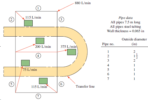
880 L/min 115 L/min Pipe data All pipes 7.5 m long All pipes steel tubing Wall thickness - 0.065 in Outside diameter (in) Pipe no. 200 L/min 375 L/min\ 4 75 L/min 1 115 L/min" Transfer line
Step by Step Solution
3.34 Rating (157 Votes )
There are 3 Steps involved in it
Fluid is a coolant sg 092 200 10 3 Pas Reynolds numbers and relative r... View full answer

Get step-by-step solutions from verified subject matter experts