

The Brayton cycle shown in Figure P16.61 is the idealized cycle for a gas turbine or jet
Question:
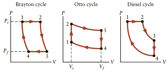
The Brayton cycle shown in Figure P16.61 is the idealized cycle for a gas turbine or jet engine. Consider an engine using the Brayton cycle that operates on 0.070 mol of ideal gas between the pressures Pi = P1 = P2 = 4.9 atm and Pf = P3 = P4 = 3.5 atm with volumes V1 = 0.50 L, V2 = 1.00 L, V3 = 1.22 L, and V4 = 0.61 L. Retain three significant figures in all calculations.
(a) Determine the work done for the displacements 1→ 2 and 3 → 4.
(b) Determine the temperature of the ideal gas at each point.
(c) Calculate the work done for the adiabatic expansion 2 → 3 and contraction 4 → 1. Consider the change in internal energy.
(d) What is the total work done by one cycle?
(e) Determine the amount of heat flowing in, QH - Q1 → 2 during the isobaric expansion and the heat flowing out of the gas during the isobaric contraction, QC → Q3 → 4. The specific heat per mole for an ideal gas under constant pressure is given by CP = CV + R.
(f) Determine the efficiency for this Brayton engine (Eq. 16.18). The heat loss and friction in a real Brayton engine will reduce this ideal efficiency. (e) Calculate and compare to the efficiency of a Carnot engine running between the same high and low temperatures.
Figure P16.61
Step by Step Answer:
The cycle consists of two isobaric processes and two adiabatic ones Assuming an ideal gas ...View the full answer


College Physics Reasoning and Relationships
ISBN: 978-0840058195
2nd edition
Authors: Nicholas Giordano
