

The Otto cycle shown in Figure P16.61 is the idealized cycle for an internal combustion automobile engine.
Question:
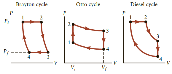
The Otto cycle shown in Figure P16.61 is the idealized cycle for an internal combustion automobile engine. Consider an engine using the Otto cycle that operates on 0.070 mol of ideal gas between the volumes Vi = V1 = V2 = 0.2 L and Vf = V3 = V4 = 1.6 L.
(a) In which parts of the cycle (1 → 2, 2 → 3, 3 → 4, 4 → 1) is work done on or by the system? In which parts does heat flow into or out of the system?
(b) The lowest temperature is 323 K at point 4, where the exhaust valve is open and the pressure is 1.0 atm. Find the temperature at point 1. Use Equation 16.10 to first find the pressure of the ideal gas. Assume that y = 5/3.
(c) The combustion of fuel in stroke 1 → 2 supplies 1000 J of energy to the gas. Calculate the change in temperature of the gas and find the temperature at point 2.
(d) What is the pressure at point 2?
(e) Find the pressure and temperature at point 3, the end of the “power stroke.”
(f) Determine the heat loss during stroke 3 → 4.
(g) Determine the efficiency for this Otto engine (Eq. 16.18). The heat loss and friction in a real Otto engine will reduce this ideal efficiency.
(h) Calculate and compare to the efficiency of a Carnot engine running between the same high and low temperatures.
Figure P16.61
Step by Step Answer:
The ideal gas law can be used to model the gas in an engine as it moves from state to state The PV diagram in Figure P1659 also provides important con...View the full answer


College Physics Reasoning and Relationships
ISBN: 978-0840058195
2nd edition
Authors: Nicholas Giordano
