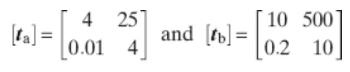
All Matches
Solution Library
Expert Answer
Textbooks
Search Textbook questions, tutors and Books
Oops, something went wrong!
Change your search query and then try again
Toggle navigation
FREE Trial
S
Books
FREE
Tutors
Study Help
Expert Questions
Accounting
General Management
Mathematics
Finance
Organizational Behaviour
Law
Physics
Operating System
Management Leadership
Sociology
Programming
Marketing
Database
Computer Network
Economics
Textbooks Solutions
Accounting
Managerial Accounting
Management Leadership
Cost Accounting
Statistics
Business Law
Corporate Finance
Finance
Economics
Auditing
Ask a Question
Search
Search
Sign In
Register
study help
computer science
systems analysis design
Questions and Answers of
Systems Analysis Design
A ball valve without an actuator cannot fail in such a way that it causes a false trip. What is the safe failure rate for the ball valve?
A flame detector used in burner management application falsely sees a flame when there is none. How would that failure mode be classified?
A gas detector used in a flammable gas shutdown function falsely indicates the presence of flammable gas. How would that failure mode be classified?
A safety PLC communicates shutdown status to the operator via a communication link. If this link fails to communicate, how would that failure mode be classified?
A SIF has a remote actuated valve energized and open. The valve must close when a demand is detected. The valve is fitted to a piston-type pneumatic actuator that has an O-ring seal around the
A manufacturer field-return data system shows six failures were reported in the last 5 years, with a total estimated operating time of 939,256 hours. If it is assumed that 40% of actual field
Based on data from a manufacturers field-return data system, an estimated 15 field failures occurred. If the estimate of field operational hours for the device is 3,000,000 hours, what is the point
A site-failure data-collection system has been established. Failures are recorded when a work order is generated to send a failed device to the manufacturer for analysis and/or repair. What potential
Cycle testing using the B10 method results in a dangerous failure rate of 0.2 FITS for a solenoid valve. Is this failure rate prediction valid for use in a low-demand process industry application?
A component database is created to perform FMEDA. The data have been calibrated based on cycle test results. Would the result from this FMEDA be suitable for low-demand process industry applications?
A component database created for FMEDA is based on process industry field failure data. Would this database be expected to generate realistic process industry failure data predictions?
Does FMEDA-based failure rate data include failure rates due to anticipated human error?
What is the failure rate of an electronic switching regulator in low power applications using environmental profile 1 from the Electrical Mechanical Component Reliability Handbook (EMCRH), as shown
What is the failure rate of a mechanical elastomer ring, U-Cup, used in a dynamic application at 350 kPa (kilopascal) in an environmental profile 1 from the EMCRH, as shown in Figure 7-4?
Can an FMEDA be used to predict the proof test coverage of a specific proof test?
A LOPA has indicated that a demand would occur every 10 years on average for a particular process hazard. Although most automatic diagnostics execute every minute, the worst-case time period for
A set of nonredundant (1oo1) safety equipment is used to construct an element used in a SIF. Demands are expected every minute. Automatic diagnostic time is given as 30 seconds.What is the HFT? What
A set of nonredundant (1oo1) safety equipment is used to construct an element used in a SIF. Demands are expected every minute. Diagnostic time is given as 1 second. The equipment is programmed to
A device is to be used as an element in a SIF in low-demand mode. The failure rates are given as:What is the SFF? If this were a Type B component in a 1oo1 architecture, what SIL level would the
A dual redundant (2oo2) design has what level of HFT?
A 2oo3 safety architecture has what level of HFT?
A motor controller is required as the final element in a SIL 2 safety function. The only product available with IEC 61508 certification will not meet functional requirements. What steps must be taken
Two smart transmitters have been selected for a SIF design. The logic solver is programmed to trip if either transmitter indicates a dangerous condition (1oo2). The manufacturer’s data sheet lists
Two smart transmitters are intended to be used for a SIF design. The IEC 61508 certificate states “systematic capability of SC 2.” Can two of these transmitters be used for a SIL 3 application?
A final element assembly is being designed consisting of a solenoid valve, a pneumatic actuator, and a trunnion ball valve. The IEC 61508 certificate for the solenoid valve states that the product
International safety standards require that operating companies follow the SIS safety life cycle specifically as outlined in the respective standard.A. True B. False
The SIS safety-life-cycle process can:A. Reduce SIS costs B. Increase process safety C. Help insure that regulations are met D. Provide an example of “good engineering practices”E. All the above
Why should a company pay attention to IEC 61508 and IEC 61511?A. It is legally required in some countries B. It can save money on safety systems C. Owners/operators often require compliance D. A
According to the SIS safety life cycle in IEC 61511, when should a process hazards analysis be conducted?A. After the project scope is defined and the piping and instrumentation drawings (P&ID) are
In the SIS safety life cycle, an SRS is done:A. After defining the project scope B. After the hazard and risk analysis phase C. Throughout the phases of the life cycle D. After overall safety
Which of the following methods is not usually part of the analysis phases of the safety life cycle?A. LOPA B. SIL verification analysis C. Hazard and operability study (HAZOP)D. Risk analysis
What parts of the SIS safety life cycle are subject to functional safety management?I. The analysis phase II. The operation phase III. Only the phases before commissioning IV. The design phase A.
In the analysis phase of the SIS safety life cycle, the following activity is performed:A. Install the SIS B. Analyze risk C. Decommission the SIS D. Operation and validation planning E. SIS
When does the safety life cycle end?A. It never ends B. When the project is fully commissioned C. When the safety system is decommissioned D. When the safety system is proven through use
Compared to control system design, there are special considerations and additional requirements for SIS design, including:I. The need to meet international standards II. Careful consideration of
An SIS typically performs the following functions:I. Reads sensors and performs optimization calculations II. Generates outputs to maintain process variables close to set points III. Executes
An SIS may include:A. Sensors B. Logic solvers C. Final elements D. All the above
In a de-energize-to-trip system, a loss of power supply failure is considered:A. Impossible B. Fail-danger C. Not a failure D. Fail-safe
How does a SIF most typically reduce risk?A. Reduces the likelihood of harm B. Reduces the magnitude of harm C. Satisfies legal requirements D. Satisfies managerial requirements
Which safety standards address SIL selection methods?I. IEC 61508 II. IEC 61511 III. ISO 9000 IV. ISA-84.00.01-2004 A. I and IV only B. I, II, and IV only C. All four items D. I and II only
Should a fire and gas system that performs a mitigation function be classified as an SIS?A. Yes – It reduces risk.B. No – These systems are not classified as an SIS.
A cause-and-effect diagram illustrates logic for a function where two valves will be closed and a pump will be de-energized when either of two pressure sensors detects that pressure in a vessel is
The complex power \(S_{\mathrm{L}}\) delivered to the load \(Z_{\mathrm{L}}\) in Figure P16-17 is \(20+j 20 \mathrm{kVA}\). The source produces an average power of \(22 \mathrm{~kW}\) and the line
In the balanced three-phase circuit in Figure P16-42 , the line impedance is \(Z_{\mathrm{W}}=1+j 5 \Omega /\) phase and the average power delivered to the load is \(25 \mathrm{~kW}\) at a lagging
In Figure P16-51, the three buses are interconnected by transmission lines with wire impedances of \(Z_{\mathrm{W}_{1}}=150+j 600\) \(\Omega /\) phase and \(Z_{\mathrm{W} 2}=200+j 1200 \Omega /\)
Given the load circuit in Figure P16-3, find the complex power delivered to the load impedance \(Z\), when:(a) \(\mathbf{V}=150
Each row in the table shown in Figure P11-69. refers to a firstorder circuit with an impulse response \(h(t)\) and a step response \(g(t)\). Fill in the missing entries in the table.
Find the inverse transforms of the following functions:(a) \(F_{1}(s)=\frac{(s+10)(s+100)(s+100000)}{(s+1)(s+1000)(s+10000)}\)(b) \(F_{2}(s)=\frac{(s+1000)(s+100000)}{(s+10000)^{2}}\)
Find the transform \(F\) ( \(s\) ) from the pole-zero diagram of Figure P9=32. \(K\) is 5 .
Find the transform \(F(s)\) from the pole-zero diagram of Figure P9=33 . \(K\) is \(5 \times 10^{6}\). Use MATLAB to find the corresponding waveform \(f(t)\).
In this problem, we look at the role of a pole or zero at the origin. The three pole-zero diagrams in Figure P9=34 vary only in the fact that there is a pole, zero, or nothing at the origin. Find the
The switch in Figure P9=37. has been closed for a long time and is opened at \(t=0\). The circuit parameters are \(R=\) \(22 \mathrm{k} \Omega, L=220 \mathrm{mH}\), and \(V_{\mathrm{A}}=10
The switch in Figure P \(9=3 \underline{8}\) has been in position A for a long time and at \(t=0\) it is moved to position \(\mathrm{B}\). The circuit parameters are \(R=100 \Omega, L=200
The switch in Figure P9-41 has been open for a long time and is closed at \(t=0\). The circuit parameters are \(R=\) \(50 \Omega, L=50 \mathrm{mH}, C=5 \mu \mathrm{F}\), and \(V_{\mathrm{A}}=1000
The switch in Figure P9-41 has been open for a long time and is closed at \(t=0\). The circuit parameters are \(R=500\) \(\Omega, L=2.5 \mathrm{H}, C=25 \mu \mathrm{F}\), and \(V_{\mathrm{A}}=500
The switch in Figure P9-43 has been closed for a long time and is opened at \(t=0\).(a) Find the circuit differential equation in \(v_{\mathrm{C}}(t)\) and the initial conditions \(i_{\mathrm{L}}\)
The switch in Figure P9=43 has been open for a long time and is closed at \(t=0\).(a) Find the circuit differential equation in \(i_{\mathrm{L}}(t)\) and the initial conditions
The \(R L C\) circuit in Figure \(\mathrm{P}_{9}=45\) is in the zero state when at \(t=0\) an exponential source, \(v_{\mathrm{S}}(t)=V_{\mathrm{A}} e^{-\alpha t} \mathrm{~V}\), is suddenly connected
Repeat Problem 9-45 when an exponential source, \(v_{\mathrm{S}}\) \((t)=15\left(1-e^{-100 t}\right) \mathrm{V}\), is suddenly connected to the circuit.Data From Problem 9-45The \(R L C\) circuit in
For the inverting OP AMP circuit shown in Figure P9-4.7., write a differential equation for \(v_{\mathrm{O}}(t)\) in terms of the elements and \(v_{\mathrm{S}}(t)\). Assume \(v_{\mathrm{C}}(0)=0\).
Steven Butterworth, a British engineer, 1885-1958, discovered a method of designing electric filters. He was quoted saying "An ideal electrical filter should not only completely reject the unwanted
In this problem, we wish to understand the behavior of a singlepole on the real axis. Consider the simple \(R C\) circuit shown in Figure P9=57. The only energy in the circuit is an initial voltage
Design a series \(R L C\) circuit so that the equivalent impedance \(Z_{\mathrm{EQ}}(s)\) has the pole-zero diagram shown in Figure P10-5 . The inductor must be \(1 \mathrm{H}\).
A manufacturer offers the circuit shown in Figure P10-13. The specification sheet states that all of the pole-zero diagrams shown are obtainable by selecting the appropriate terminals and opening or
Consider the circuit shown in Figure P10-15.(a) Find \(V_{\mathrm{T}}(s)\) and \(Z_{\mathrm{T}}(s)\).(b) Plot the poles and zeros of \(Z_{\mathrm{T}}(s)\).(c) Let \(V_{1}(s)=V_{\mathrm{A}} / s\) and
Find the network function \(K=V_{2}(s) / V_{1}(\) \(s)\) for the circuit shown in Figure P10-21. Then identify the poles and zeros of the network function. choose values of \(R\) and \(C\) so that
For the dependent source circuit shown in Figure P10-25, use superposition to find \(V_{\mathrm{O}}(s)\).
The Thévenin voltage of the circuit in Figure P10-27 has the pole-zero diagram shown.(a) If \(R=100 \mathrm{k} \Omega\), what are the values of \(C_{1}\) and \(C_{2}\) ?(b) Is the system stable?
The OP AMP circuit shown in Figure P10-31 is purported to be a low-pass filter with a cutoff frequency at the single pole of the circuit and the dc gain given by the ratio of the two resistors.(a)
The three voltage phasors pictured in Figure P8-11 all have the same magnitude of \(10 \mathrm{~V}\) and each is shifted from an axis by \(-45^{\circ}\). Yet these three phasors are all related. One
Find the equivalent impedance \(Z\) in Figure P8-14.(a) If \(\omega=5 \mathrm{krad} / \mathrm{s}\), what two elements ( \(R, L\), and/or \(C\) ) could be used to replace the phasor circuit?(b)
The passive network in Figure P8-16 can be connected in several different ways to attain various impedances. It is purported that the circuit is in resonance in two of the three possible connections
The equivalent impedance in Figure P8-20 is known to be \(Z=30+j 90 \Omega\). Find the impedance of the inductor.
The circuit in Figure P8-22 is excited by a 10-krad/s sinusoidal source. As the circuit's designer, select a capacitor \(C\) such that the impedance \(Z\) looking into the circuit is all real.
The circuit in Figure P8-26 is operating in the sinusoidal steady state. Find the phasor current and the two element voltages. Is the phasor voltage across the capacitor leading or lagging the
The circuit in Figure P8-29. is operating in the sinusoidal steady state with \(i_{\mathrm{S}}(t)=I_{\mathrm{A}} \cos (\omega t)\). Derive general expressions for the steady-state responses
Select \(Z_{\mathrm{X}}\) in Figure P8-32 so that \(\mathbf{V}_{\mathrm{R}}=100 \angle 0^{\circ}\) V. Validate your solution using Multisim.
The circuit in Figure P8-33 is operating in the sinusoidal steady state. Find the steady-state responses \(v_{\mathrm{X}}(t)\) and \(i_{\mathrm{X}}(t)\).
The circuit in Figure P8-35 is driven by a 100\(\mathrm{krad} / \mathrm{s}\) source and is operating in the sinusoidal steady-state. Use Multisim to find the steady-state phasor response
The circuit in Figure P8-36 is operating in the sinusoidal steady state.(a) Use superposition to find the response \(v_{\mathrm{X}}(t)\).(b) Use Multisim to validate your response in part (a).
The circuit in Figure P8-3 3 is operating in the sinusoidal steady state.(a) Use superposition to find the response \(v_{\mathrm{X}}(t)\).(b) Validate your answer using Multisim.
The circuit in Figure P8-3.9 is operating in the sinusoidal steady state. Use superposition to find the response \(v\) \(\mathrm{x}(t)\).
The bridge circuit in Figure P8-40 is operating in the sinusoidal steady state.(a) Find the Thévenin equivalent circuit seen by \(Z_{\mathrm{X}}\).(b) Is the bridge balanced, that is,
The circuit in Figure P8-43 is operating in the sinusoidal steady state. Use the unit-output method to find the phasor responses \(\mathbf{V}_{\mathrm{X}}\) and \(\mathbf{I}_{\mathrm{X}}\).
For the circuit in Figure P8-44, do the following:(a) Find the phasor Thévenin equivalent of the source circuit to the left of the interface by hand. Then use Multisim to validate your Thévenin
(a) The circuit in Figure P8-45 is operating in the sinusoidal steady state. When \(Z_{\mathrm{L}}=\mathrm{o}\), the phasor current at the interface is \(\mathbf{I}=4.8-j 3.6 \mathrm{~mA}\). When
(a) Design a linear source circuit that will deliver an output phasor \(\mathbf{V}_{\mathrm{O}}=30 \angle 45^{\circ} \mathrm{V}\) when an input voltage \(v_{\mathrm{S}}(t)\) \(=120 \cos (377 t)
Refer to the \(R L C\) series circuit shown in Figure P8-4.9.(a) What is the maximum output voltage \(v_{\mathrm{O}}(t)\) and at what frequency does it occur? Use Multisim and do an ac sweep from
The circuit in Figure P8-50 is operating in the sinusoidal steady state with \(\omega=1 \mathrm{krad} / \mathrm{s}\). Use node-voltage analysis to find the steady-state response
For the phasor circuit in Figure P8-51:(a) Use node-voltage analysis to find the steady-state phasor response \(\mathbf{V}_{\mathrm{O}}\).(b) Use mesh-current analysis to find the steady-state phasor
Use mesh-current analysis to find the phasor branch currents \(\mathbf{I}_{1}, \mathbf{I}_{2}\), and \(\mathbf{I}_{3}\) in the circuit shown in Figure P8-54.
The circuit in Figure P8-59. is operating in the sinusoidal steady state. The output is measured as \(\mathbf{V}_{\mathrm{O}}=300+j\) 200. Find the input \(V_{S}\) that will produce the output
The bridge circuit in Figure P8-63 is operating in the sinusoidal steady state. Find \(\mathbf{I}_{\mathrm{AB}}\).
In the circuit shown in Figure P8-65, there is an unknown element \(Z_{\mathrm{X}}\). The task is to determine the phasor gain and the output impedance \(Z_{\text {OUT }}\) of the circuit. Before
The load in Figure P8-69. needs to be designed for maximum power transfer.(a) Find the maximum available average power at the interface shown in the figure.(b) Specify the load required to extract
A power transmission circuit with a source voltage of \(\mathbf{V}_{\mathrm{S}}=880\) \(+j\) o V can be modeled as shown in Figure P8-73 .(a) Find the average power produced by the source, lost in
A 1-k \(\Omega\) resistor models an important and sensitive laboratory instrument. The instrument measures a desired signal that varies from \(1 \mathrm{~Hz}\) to \(500 \mathrm{~Hz}\). However,
Select values of \(L\) and \(C\) in Figure P8-7.5 so that the input impedance seen by the voltage source is \(50+j 0 \Omega\) when the frequency is \(\omega=10^{6} \mathrm{rad} / \mathrm{s}\). For
Find the Laplace transform of the following signals and locate the poles and zeros of \(F(s)\).(a) \(f(t)=-8 u(t)\).(b) \(f(t)=0.5 t u(t)\).(c) \(f(t)=10 e^{-20000 t} u(t)\).
Find the Laplace transform of the following signals and locate the poles and zeros of \(F(s)\).(a) \(f(t)=-10 \mathrm{~d} \delta(t) / d t\)(b) \(f(t)=120 \cos (377 t) u(t)\).(c)
Showing 600 - 700
of 3888
1
2
3
4
5
6
7
8
9
10
11
12
13
14
15
Last