

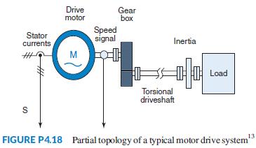
Question: A drive system with elastically coupled load (Figure P4.18) has a motor that is connected to the load via a gearbox and a long shaft.
A drive system with elastically coupled load (Figure P4.18) has a motor that is connected to the load via a gearbox and a long shaft.
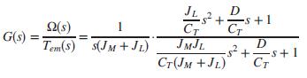
The system parameters are: JM = drive-side inertia= 0.0338 kg-m2, JL = load-side inertia = 0.1287 kg-m2, K = CT = torsional spring constant = 1700 N-m/rad, and D = damping coefficient = 0.15 N-m-s/rad. This system can be reduced to a simple two inertia model that may be represented by the following transfer function, relating motor shaft speed output, Ω(s), to electromagnetic torque input (Thomsen, 2011):
Assume the system is at standstill at t = 0, when the electromagnetic torque, Tem, developed by the motor changes from zero to 50 N-m. Find and plot on one graph, using MATLAB or any other program, the motor shaft speed, ω(t), rad/sec, for the following two cases:
a. No load torque is applied and, thus, ω = ωnl.
b. A load torque, TL = 0.2ω(t) N-m is applied and ω = ωL.
+ CT JMJL + s+1 2(s) 1 G(s) Tem(s) s(JM + JL) Cr(JM +JL) s+1
Step by Step Solution
3.40 Rating (175 Votes )
There are 3 Steps involved in it

Get step-by-step solutions from verified subject matter experts