Consider the plant of Problem 9.2-1, which has the transfer function, from Example 9.5, G ( z
Question:
Consider the plant of Problem 9.2-1, which has the transfer function, from Example 9.5,
G(z)=z−1zz[1s2(s+1)]=0.00484z+0.00468z2−1.905z+0.905
(a) Using the pole-assignment design, find the gain matrix K required to realize the closed-loop characteristic equation with zeros that have the damping ratio ζ=0.707 and the time constant τ=0.8 s
(b) To verify the design, show that (9-15) yields the desired closed-loop characteristic equation.
Equation 9-15
(c) Draw a flow graph of the form of Fig. 4-20 for the plant. Then add the feedback gains of part (a).
Fig. 4-20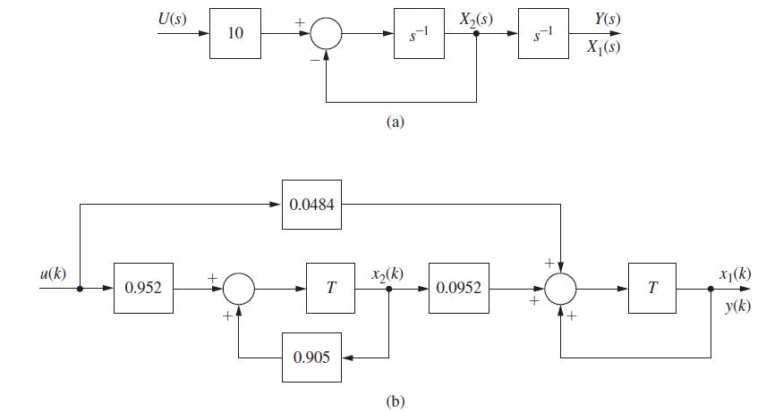
(d) Write the state equations for the flow graph of part (c), to verify the system matrix (A−BK) found in part (b).
(e) Find all loop gains in the flow graph of part (c). Then use Mason's formula to verify that the flow graph of part (c) has the characteristic equation of parts (a) and (b).
Problem 9.2-1
The plant of Example 9.1 has the state equations given (9-1). Find the gain matrix K required to realize the
closed-loop characteristic equation with zeros which have a damping ratio 1 of 0.46 and a time constant v
of 0.5 s. Use pole-assignment design.
Example 9.1
In this example the servomotor system of Fig. 9-1, with the state equations given in (9-1), will
be considered. With full-state feedback, the characteristic equation is given in (9-6). Consider
first that the closed-loop system is implemented with the usual unity feedback; then K1 = 1 and
K2 = 0. From (9-6), the characteristic equation is given by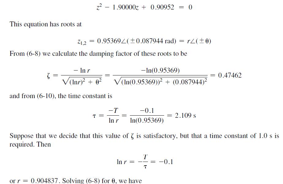

![From (9-9), K = ac(z) = z 2rcose z + r 105.0833[2 ( + A) + 1.0] = 105.0833[0.818731 - (1.77864) + 1.0] = =](https://dsd5zvtm8ll6.cloudfront.net/images/question_images/1705/5/8/0/16165a91681d2b931705580161490.jpg)
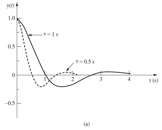
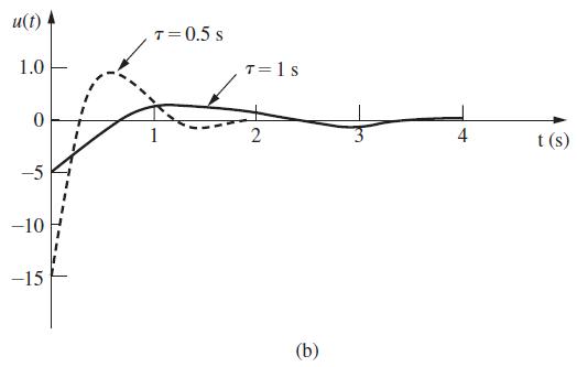
Equation 9-1![x(k + 1) = y(k) = 1 0.095163 0 0.904837 [10]x (k) x(k) + 0.0048374 0.095163 u(k) (9-1)](https://dsd5zvtm8ll6.cloudfront.net/images/question_images/1705/5/8/0/24665a916d6974fa1705580246529.jpg)
Example 9.5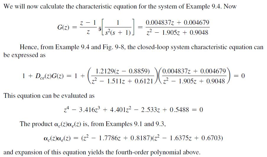
Step by Step Answer:

Digital Control System Analysis And Design
ISBN: 9780132938310
4th Edition
Authors: Charles Phillips, H. Nagle, Aranya Chakrabortty


