

Question: A block diagram for a divider that divides an 8-bit unsigned number by a 4-bit unsigned number to give a 4-bit quotient is shown subsequently.
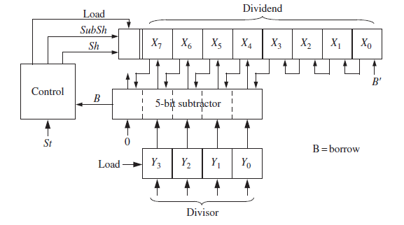
A block diagram for a divider that divides an 8-bit unsigned number by a 4-bit unsigned number to give a 4-bit quotient is shown subsequently. The Xi inputs to the subtractors are shifted over one position to the left. This means that the shift-and-subtract operation can be completed in one clock time instead of two. Depending on the borrow from the subtractor, a shift or shift-and-subtract operation occurs at each clock time, and the division can always be completed in four clock times after the registers are loaded. Ignore overflow. When the start signal (St) is 1, the X and Y registers are loaded. Assume that the start signal (St) is 1 for only one clock time. Sh causes X to shift left with 0 fill. SubSh causes the subtractor output to be loaded into the left part of X and at the same time the rest of X is shifted left.
(a) Draw a state graph for the controller (five states).
(b) Complete the Verilog code that follows. Registers and signals should be of type unsigned so that overloaded operators may be used. Write behavioral code that uses a single always block.
module divu(dividend, divisor, St, clk, quotient);
input[7:0] dividend;
input[3:0] divisor;
input St,clk;
output[3:0] quotient;
.
.
.
endmodule
Dividend Load SubSh X7 X5 X4 X2 , Xo X6 X3 Sh B' Control 5-bit subtractor St B=borrow Y Y2 Y1 YO Load Divisor
Step by Step Solution
3.52 Rating (166 Votes )
There are 3 Steps involved in it
a b module divudividend divisor St clk quotient input 70 dividend input ... View full answer

Get step-by-step solutions from verified subject matter experts