Refer to the IC counter circuit in Figure 7-106(a): (a) Draw the state transition diagram for the
Question:
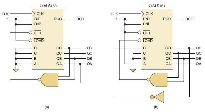
Refer to the IC counter circuit in Figure 7-106(a):
(a) Draw the state transition diagram for the counter’s QD QC QB QA outputs.
(b) Determine the counter’s modulus.
(c) What is the relationship of the output frequency of the MSB to the input CLK frequency?
(d) What is the duty cycle of the MSB output waveform?
Figure 7-106

Transcribed Image Text:
CLK 1 74ALS163 CLK ENT ENP DCBA CLR LOAD (a) RCO QC QB QA RCO QC QB -QA CLK 1 74ALS161 CLK ENT ENP CLR LOAD DCBA (b) RCO QC QB QA RCO QD QC QB QA
Step by Step Answer:

This question has not been answered yet.
You can Ask your question!
Related Book For 

Digital Systems Principles And Application
ISBN: 9780134220130
12th Edition
Authors: Ronald Tocci, Neal Widmer, Gregory Moss
Question Posted:
Students also viewed these Computer science questions
-
Repeat Problem 7-21 for the IC counter circuit in Figure 7-106(b). Data from Problem 7-21 Refer to the IC counter circuit in Figure 7-106(a): (a) Draw the state transition diagram for the counters QD...
-
Refer to the IC counter circuit in Figure 7-107(a). (a) Draw the timing diagram for outputs QD QC QB QA. (b) What is the counters modulus? (c) What is the count sequence? Does it count up or down?...
-
Refer to the IC counter circuit in Figure 7-107(b): (a) Describe the counters output on QD QC QB QA if START is LOW. (b) Describe the counters output on QD QC QB QA if START is momentarily pulsed LOW...
-
What is the output of the following? A. 1223445 B. 2445 C. 22445 D. 223445 E. 2233445 F. None of the above. public class InitOrder { } {System.out.print("1"); } static System.out.print("2"); } public...
-
If the reciprocal method is conceptually superior, why dont all firms use it?
-
What the major types of merchants and agents used in indirect exporting?
-
Why might someone use the corporate model even though the dividend model could be used? AppendixLO1
-
The Chang Company is considering the purchase of a new machine to replace an obsolete one. The machine being used for the operation has a book value and a market value of zero. However, the machine...
-
3. The cost of drilling a natural gas well is $250,000. 10% of the revenue from the sale of natural gas from this particular well constitutes operating expenses. If found, natural gas from a highly...
-
A dam is to be constructed using the cross-section shown. Assume the dam width is w = 160 ft. For water height H = 9 ft. calculate the magnitude and line of action of the vertical force of water on...
-
Examine the 74HC165 function table and determine (a) The conditions necessary to load the register with parallel data; (b) The conditions necessary for the shifting operation.
-
How would you connect two 74ALS174s to operate as a 12-bit shift register?
-
Glucose reacts with ammonia in the presence of a trace of acid to give predominantly -D- glucopyranosylamine. Propose a reasonable mechanism for this transformation. Why is only the hydroxy group at...
-
BillyHardware takes pride as the "shop around the corner" that can compete with the big-box home improvement stores by providing good service from knowledgeable sales associates (many of whom are...
-
Candles R Us is a retailer that sells every kind of candleimaginable. The different types of candles are stored indepartments that all take up the same amount of space. Given theavailable warehouse...
-
Describe the specific tasks you performed your first week. Describe your work environment (formal, casual, dress attire, etc.). What do you like about where you are working? What type of...
-
Using the topic Resources, discuss the factors that drive family purchase decisions. Explain why this information is important to marketers and discuss how they use it when marketing products....
-
Professional development for school administrators: -cite at least one source (Pick any one topic -Leadership or Communication, School Climate or Collaboration or Emotional Literacy, or any suitable...
-
With regard to development, what would be the dire consequences if polycomb group complexes did not function properly?
-
One study found that the elderly who do not have children dissave at about the same rate as the elderly who do have children. What might this finding imply about the reason the elderly do not dissave...
-
A material of resistivity p is formed into the shape of a truncated cone of altitude h as shown in Figure P27.72. The bottom end has radius b, and the top end has radius a. Assume that the current is...
-
The dielectric material between the plates of a parallel plate capacitor always has some nonzero conductivity &. Let A represent the area of each plate and d the distance between them. Let 4...
-
The currentvoltage characteristic curve for a semiconductor diode as a function of temperature T is given by the equation I = I0 (ee/kBT 1) Here the first symbol e represents Eulers number, the base...
-
Jimmy earned $85,000 in salary from his job as an engineer. He earned $3,000 in interest income. He made RPP contributions of $2,119 and contributed $15,000 to his RRSP. Given the following schedule...
-
Question 3 A . Bonika Sdn Bhd ( BSB ) manufactures small camping tents. BSB produced 3 , 0 0 0 units during the year. These camping tents sell for RM 1 5 0 each. BSB had 5 0 0 units in finished goods...
-
Required information (The following information applies to the questions displayed below.) Davis Stores sells clothing in 15 stores located around the southwestern United States. The managers at...

Study smarter with the SolutionInn App


