

Question: Use the FPGA illustrated below to implement a full adder. Label the outputs clearly. Draw lines between the cells to indicate a connection between the
Use the FPGA illustrated below to implement a full adder. Label the outputs clearly. Draw lines between the cells to indicate a connection between the logic functions.
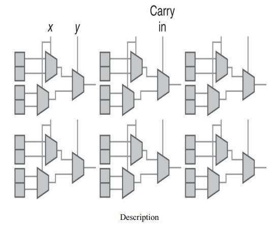
X y Carry in Description B
Step by Step Solution
★★★★★
3.42 Rating (149 Votes )
There are 3 Steps involved in it
1 Expert Approved Answer
Step: 1 Unlock

The image youve provided depicts a simplified FPGA FieldProgrammable Gate Array architecture where t... View full answer
Question Has Been Solved by an Expert!
Get step-by-step solutions from verified subject matter experts
Step: 2 Unlock
Step: 3 Unlock