

Question: As described in Sects. 7.2 and 7.4, FRFs are often measured using impact testing. In this approach, an instrumented hammer is used to excite the
As described in Sects. 7.2 and 7.4, FRFs are often measured using impact testing. In this approach, an instrumented hammer is used to excite the structure and a transducer is used to record the resulting vibration.
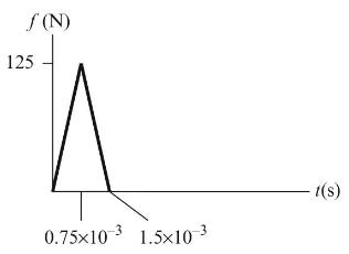
Fig. P7.6 Impulsive force profile for impact test.
Use Euler integration to determine the displacement due to the triangular impulsive force profile shown in Fig. P7.6. The force excites a single degree of freedom spring-mass-damper system with \(m=2 \mathrm{~kg}, k=1.1 \times 10^{6} \mathrm{~N} / \mathrm{m}\), and \(c=83 \mathrm{~N}-\mathrm{s} / \mathrm{m}\). For the Euler integration, use a time step of \(1 \times 10^{-5} \mathrm{~s}\) and carry out your simulation for \(0.2 \mathrm{~s}(20,000\) points).
(a) Plot both the force \((\mathrm{N})\) versus time (s) and displacement ( \(\mu \mathrm{m})\) versus time.
(b) Determine the maximum displacement (in \(\mu \mathrm{m}\) ) and the time at which this displacement occurs.
Sects. 7.2:
Sects. 7.3:
125 (N) 0.75x10 3 1.510 3 t(s)
Step by Step Solution
There are 3 Steps involved in it

Get step-by-step solutions from verified subject matter experts