

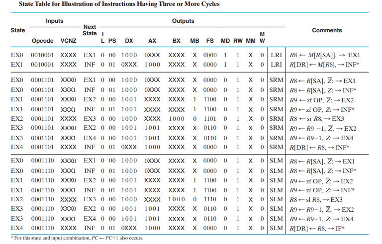
Question: List the control logic state table entries for the multiple- cycle computer (see Tables 8-12, 8-13 and 8-15) that implement the following register transfer statements.
List the control logic state table entries for the multiple- cycle computer (see Tables 8-12, 8-13 and 8-15) that implement the following register transfer statements. Assume that in all cases the present state is EX0. If an opcode is needed, use a symbolic name based on the problem part— e.g., for part (a), opcode_a.
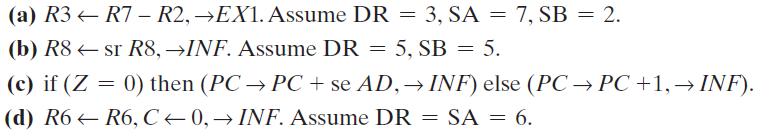
Table 8-12
![Control-Word Information for Datapath DX AX BX Code MB Code FS R[DR] R[SA] R[SB] OXXX Register 0 F = A R8 R8](https://dsd5zvtm8ll6.cloudfront.net/images/question_images/1704/5/6/8/5726599a6fc9e2ec1704568570419.jpg)
Table 8-12
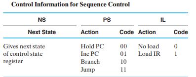
Table 8-15
(a) R3-R7 - R2, EX1. Assume DR = 3, SA = 7, SB = 2. (b) R8sr R8, INF. Assume DR = 5, SB = 5. (c) if (Z = 0) then (PC PC + se AD, INF) else (PC PC +1, INF). (d) R6-R6, C-0,INF. Assume DR = SA = 6.
Step by Step Solution
3.29 Rating (158 Votes )
There are 3 Steps involved in it
Part State Opcode VCNZ Next State a EXO 0000101 XXXX b EX0 0001101 xx... View full answer

Get step-by-step solutions from verified subject matter experts