

Question: The single- cycle computer in Figure 8-15 executes the ive instructions described by the register transfers in the table that follows. Figure 8-15 (a) Complete
The single- cycle computer in Figure 8-15 executes the ive instructions described by the register transfers in the table that follows.
Figure 8-15
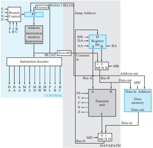
(a) Complete the following table, giving the binary instruction decoder outputs from Figure 8-16 during execution of each of the instructions:
![Instruction Register Transfer R[0] R[7] R[3] R[1] M[R[4]] R[2] R[5]+2 R[3] sl R[6] if (R([4] = 0) PC](https://dsd5zvtm8ll6.cloudfront.net/images/question_images/1704/5/6/8/2286599a5a42333e1704568225237.jpg)
Figure 8-16
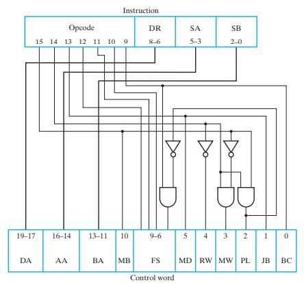
(b) Complete the following table, giving the instruction in binary for the single-cycle computer that executes the register transfer (if any field is not used, give it the value 0):
![Instruction Register Transfer R[0] R[7]+R[6] R[1] R[5]-1 R[2] sl R[4] R[3] R[3] R[4] R[2] V R[1] Opcode](https://dsd5zvtm8ll6.cloudfront.net/images/question_images/1704/5/6/8/3026599a5ee6a6b21704568300505.jpg)
V- C-Branch N-Control Z PJB LBC PC Extend Address Instruction memory Instruction IR (8:6) || IR (2:0) IR (2:0) Instruction decoder Zero fill DBAMFM RMPJB A A ABSD WWL BC CONTROL Jump Address RW- DA AA - Constant in FS N D Register file A Bus A Bus D B-BA 10 MUX B MD- Bus B Function unit F B MB Address out Data out 01 MUX D DATAPATH MW Data in Address Data memory Data out Data in
Step by Step Solution
3.45 Rating (155 Votes )
There are 3 Steps involved in it
Instruction Register Transfer DA AA BA MB FS MD RW MW R0 R7R3 000 111 011 0 1010 0 1 0 20 PL JB ... View full answer

Get step-by-step solutions from verified subject matter experts