

Question: Consider the unusual piping diagram for the four tanks in Fig. E2.22 in which both the flow rates F 1 and F 2 are split
Consider the unusual piping diagram for the four tanks in Fig. E2.22 in which both the flow rates F1and F2are split between two streams entering the upper and lower tanks (denoted by the fractions in the diagram). For the exit lines leaving the bottom of each of the four tanks through an orifice, you may assume that flow through that orifice obeys the square root dependence on the height of liquid in the tanks, as described in Section 2.4.5.
(a) Derive the mass balances for each of the four tanks, and express them as simple equations (four total) with one deriva-tive term on the left hand side.
(b) For the case of γ1 = 0.5 and γ2 = 0.5 (i.e., equal splitting of each stream), what is the resulting form of the equations? Can the levels be solved independently? Can the flow rates be used independently to adjust the heights in the tanks?
(c) For the extreme case of γ1 = 0 and γ2 = 0, what is the resulting form of the equations? Does this make sense in terms of the process schematic?
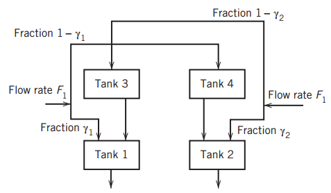
Fraction 1-Y2 Fraction 1- Y1 Tank 4 Tank 3 Flow rate F Flow rate F, Fraction Y2 Fraction y1 Tank 2 Tank 1
Step by Step Solution
3.40 Rating (163 Votes )
There are 3 Steps involved in it
T o solve the problem we start by writing the mass balance for each tank 14 To write the mass balanc... View full answer

Get step-by-step solutions from verified subject matter experts
Document Format (2 attachments)
1602_606321ef12a25_679139.pdf
180 KBs PDF File
1602_606321ef12a25_679139.docx
120 KBs Word File