Answered step by step
Verified Expert Solution
Question
1 Approved Answer
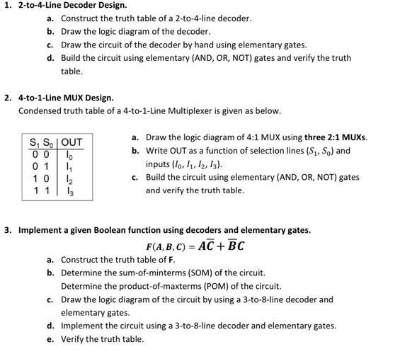
1. 2-to-4-Line Decoder Design. a. Construct the truth table of a 2-to-4-line decoder. b. Draw the logic diagram of the decoder. c. Draw the

1. 2-to-4-Line Decoder Design. a. Construct the truth table of a 2-to-4-line decoder. b. Draw the logic diagram of the decoder. c. Draw the circuit of the decoder by hand using elementary gates. d. Build the circuit using elementary (AND, OR, NOT) gates and verify the truth table. 2. 4-to-1-Line MUX Design. Condensed truth table of a 4-to-1-Line Multiplexer is given as below. S, SOUT 00 lo 01 1 10 12 1 1 13 a. Draw the logic diagram of 4:1 MUX using three 2:1 MUXS. b. Write OUT as a function of selection lines (S, S) and inputs (10, 11, 12, 13). c. Build the circuit using elementary (AND, OR, NOT) gates and verify the truth table. 3. Implement a given Boolean function using decoders and elementary gates. F(A,B,C) = AC + BC a. Construct the truth table of F. b. Determine the sum-of-minterms (SOM) of the circuit. Determine the product-of-maxterms (POM) of the circuit. c. Draw the logic diagram of the circuit by using a 3-to-8-line decoder and elementary gates. d. Implement the circuit using a 3-to-8-line decoder and elementary gates. e. Verify the truth table.
Step by Step Solution
★★★★★
3.36 Rating (149 Votes )
There are 3 Steps involved in it
Step: 1
Certainly lets start by designing a 2to4 line decoder a Truth Table Inputs A B Outputs Y0 Y1 Y2 Y30 0 1 0 0 00 1 0 1 0 01 0 0 0 1 01 1 0 0 0 1 The tru...
Get Instant Access to Expert-Tailored Solutions
See step-by-step solutions with expert insights and AI powered tools for academic success
Step: 2

Step: 3

Ace Your Homework with AI
Get the answers you need in no time with our AI-driven, step-by-step assistance
Get Started


