

Question: 1. (32 pts):The provided synchronous datapath is to be used to do the following calculation using a 4-bit unsigned integer IN: INISO OUT (2 x
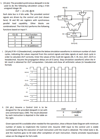
1. (32 pts):The provided synchronous datapath is to be used to do the following calculation using a 4-bit unsigned integer IN: INISO OUT (2 x IN) IN Each data bus is 4 bits wide. The pravided control signals are driven by the control unit (not shownE here)? RI and RO are registers with synchronous parallel load capability Other blocks are combinational. The 4 bit ALU performs the following functions based on input F: F[1.0 ALU Function A+ B (addition i. (16 pts) If IN-6 (hexadecimal), complete the below simulation waveforms in minimum number of clock cycles, indicating the values required from the control signals and data signals at each clock cycle in order to calculate OUT correctly. Enter the values of the multi-bit signals (N, F, RI, ALU OUT, OUT) in hexadecimal. Assume the propagation delays are all 0 (zero). Stop simulation waveforms when the 4- bit result is obtained for OUT computation. Calculate and show all arithmetic values (in hexadecimal format) ii. (16 pts.) Assume a Control Unit is to be designed for the provided datapath in (a) with one command input, CMD. The result obtained by each instruction is depicted in the table on the right. xIN Given operand IN is available when needed for the operation, show a Moore State Diagram with minimum number of states to implement the Control Unit. Assume CMD input to the control unit is stable (unchanged) during the execution of each instruction until the result is obtained. The initial state is S0, and the machine goes to S0 state after completion of each instruction. Clearly annotate input/output values on the diagram for full credit 1. (32 pts):The provided synchronous datapath is to be used to do the following calculation using a 4-bit unsigned integer IN: INISO OUT (2 x IN) IN Each data bus is 4 bits wide. The pravided control signals are driven by the control unit (not shownE here)? RI and RO are registers with synchronous parallel load capability Other blocks are combinational. The 4 bit ALU performs the following functions based on input F: F[1.0 ALU Function A+ B (addition i. (16 pts) If IN-6 (hexadecimal), complete the below simulation waveforms in minimum number of clock cycles, indicating the values required from the control signals and data signals at each clock cycle in order to calculate OUT correctly. Enter the values of the multi-bit signals (N, F, RI, ALU OUT, OUT) in hexadecimal. Assume the propagation delays are all 0 (zero). Stop simulation waveforms when the 4- bit result is obtained for OUT computation. Calculate and show all arithmetic values (in hexadecimal format) ii. (16 pts.) Assume a Control Unit is to be designed for the provided datapath in (a) with one command input, CMD. The result obtained by each instruction is depicted in the table on the right. xIN Given operand IN is available when needed for the operation, show a Moore State Diagram with minimum number of states to implement the Control Unit. Assume CMD input to the control unit is stable (unchanged) during the execution of each instruction until the result is obtained. The initial state is S0, and the machine goes to S0 state after completion of each instruction. Clearly annotate input/output values on the diagram for full credit
Step by Step Solution
There are 3 Steps involved in it

Get step-by-step solutions from verified subject matter experts