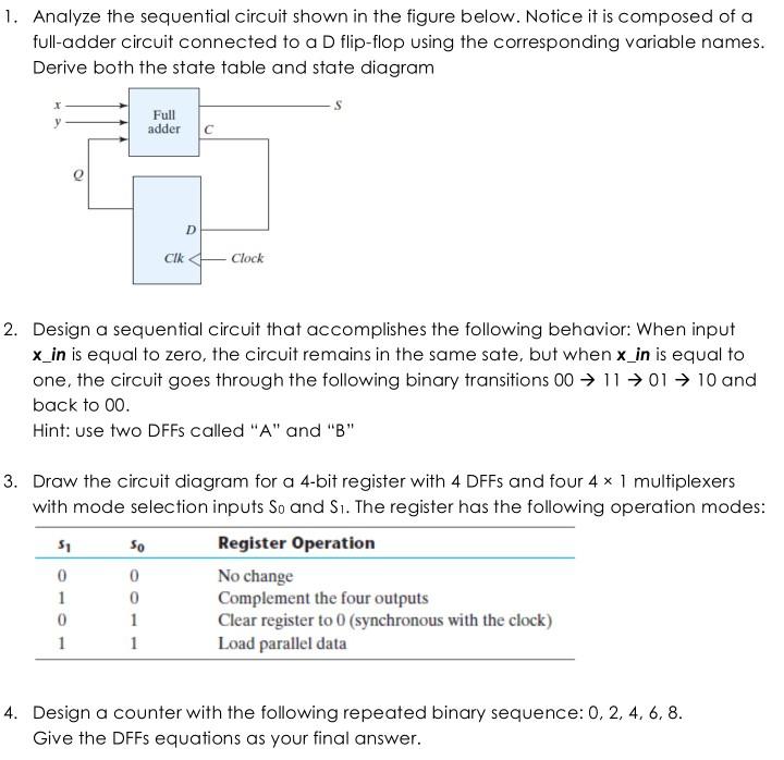
Question: 1. Analyze the sequential circuit shown in the figure below. Notice it is composed of a full-adder circuit connected to a D flip-flop using

1. Analyze the sequential circuit shown in the figure below. Notice it is composed of a full-adder circuit connected to a D flip-flop using the corresponding variable names. Derive both the state table and state diagram X 5 0 1 0 1 Full adder C 50 0 D 2. Design a sequential circuit that accomplishes the following behavior: When input x_in is equal to zero, the circuit remains in the same sate, but when x_in is equal to one, the circuit goes through the following binary transitions 00 1101 10 and back to 00. Hint: use two DFFs called "A" and "B" 0 1 1 Clk 3. Draw the circuit diagram for a 4-bit register with 4 DFFs and four 4 x 1 multiplexers with mode selection inputs So and S. The register has the following operation modes: Register Operation No change Complement the four outputs Clear register to 0 (synchronous with the clock) Load parallel data Clock 4. Design a counter with the following repeated binary sequence: 0, 2, 4, 6, 8. Give the DFFs equations as your final answer.
Step by Step Solution
3.39 Rating (155 Votes )
There are 3 Steps involved in it

Get step-by-step solutions from verified subject matter experts


