Question
1. As shown in Table 1, pricing may not be realistic for today's market but assuming the prices are realistic for this project. Only consider
1. As shown in Table 1, pricing may not be realistic for today's market but assuming the prices are realistic for this project. Only consider the material information provided in Table 1 and the design goals and specifications as outlined in this assignment sheet. All results calculated in this assignment must be based on a 2D plane stress assumption. It is up to you how you choose to design work, but your final design must be at least verified with a valid finite element analysis. The finite element analysis must be completed using ANSYS/Workbench. Plastics can experience nonlinear behaviour in some circumstances. In this work, however, assume a linear, static analysis is valid.
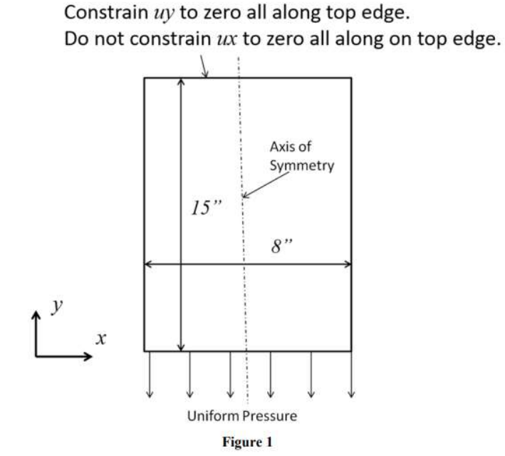
Referring to the coordinate system in Figure 1, the bracket must have a constant thickness, T, in the z-direction (the "out-of-page" direction). The idea is that the part could be cut from a constant thickness sheet of material that was either extruded or molded. Regardless of how it is manufactured, assume isotropic, elastic material properties. The allowable range for the thickness is 0.20" ? ? ? 1.75". Your design is not required to span the full 8" width for the entire 15" length. It must span the entire 8" width at the top and the bottom and it must all fit within an 8" 15" rectangular area. It cannot include locations that would produce a stress singularity for which finite element stress result would be invalid. So, sharp internal corners must be avoided. The design must be symmetric about the vertical axis shown. The 2D plane stress model must take advantage of symmetry. So, only half of the geometry is to be modeled.
Mesh the bracket with an adequate mesh for producing accurate results. Perform a linear, static analysis in ANSYS to solve for stresses and deflections. Along the top edge, the bracket is constrained from vertical (y-direction) deflection, but it is not constrained from x-direction deflection along the top edge (except at the plane of symmetry). Along the bottom edge is a uniformly distributed constant load.
You must arrive at a design that meets the specifications listed below and that you submit a valid finite element model that confirms that your design is acceptable. Minimizing part cost is also essential. Your grade will depend, in part, on the final price per part for your design.
Design Specifications:
1. When a 150-pound uniformly distributed load is applied to the bracket, the factor of safety with regard to stresses must be at least 2.0. The factor of safety can be calculated by dividing the material yield strength by the maximum von Mises stress (Equivalent Stress) in the bracket. The load is applied along the bottom horizontal surface, as shown in Figure1. Note that the total load for the entire structure must equal 150 ???. In Workbench, the load can be applied as pressure or a force. Be sure your model appropriately makes use of symmetry, and the result of the applied loading in your analysis is consistent with 150 ??? total loads applied to the entire structure. Since your taking advantage of symmetry, the load applied to the half that you model should be 75 ???.
2. Under the loading outlined in Item 1 above, the vertical direction (y-direction) deflection for any point on the bottom edge on which the load is applied cannot exceed 0.015". Suppose the model is set up according to the coordinate directions shown in Figure 1, based on the loading. In that case, the deflections along the bottom edge will be in the negative y-direction, so the maximum absolute value of the y-direction deflection for any node along the bottom surface must not exceed 0.015".


Constrain uy to zero all along top edge. Do not constrain ux to zero all along on top edge. X 15" Axis of Symmetry 8" Uniform Pressure Figure 1
Step by Step Solution
There are 3 Steps involved in it
Step: 1

Get Instant Access to Expert-Tailored Solutions
See step-by-step solutions with expert insights and AI powered tools for academic success
Step: 2

Step: 3

Ace Your Homework with AI
Get the answers you need in no time with our AI-driven, step-by-step assistance
Get Started


