Question: 1.) Describe the problem. 2) The expression of the transfer function of each filter; how you calculate the resistance R in the first two filters.

1.) Describe the problem.
2) The expression of the transfer function of each filter; how you calculate the resistance R in the first two filters.
3) Plot the magnitude response of the ideal low pass filter and the first three filters you designed on same figure.
4) Compare the first three low pass filters (ease of design, frequency response in pass band, outside pass band, and transition region).
5) Plot the magnitude response of the ideal low pass filter and the third and fourth filters you designed on same figure.
6) Compare the performance of Filter 3 and 4. Explain the advantages and disadvantages of Filter 4 (in terms of practical implementation and performance).
7) Copy and paste your Matlab code.
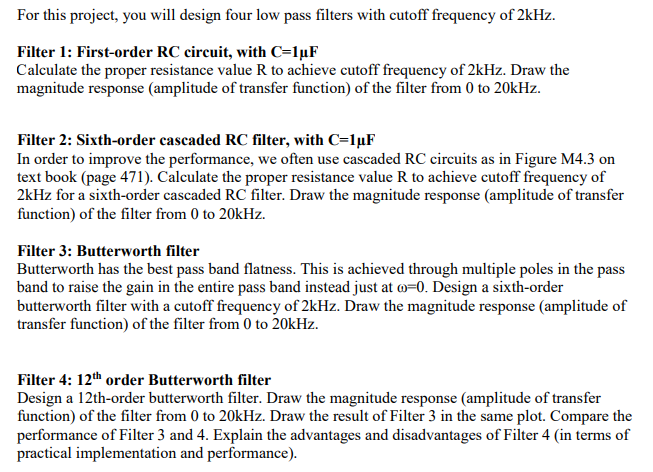
For this project, you will design four low pass filters with cutoff frequency of 2kHz. Filter 1: First-order RC circuit, with C-luF Calculate the proper resistance value R to achieve cutoff frequency of 2kHz. Draw the magnitude response (amplitude of transfer function) of the filter from 0 to 20kHz. Filter 2: Sixth-order cascaded RC filter, with C-luF In order to improve the performance, we often use cascaded RC circuits as in Figure M4.3 on text book (page 471). Calculate the proper resistance value R to achieve cutoff frequency of 2kHz for a sixth-order cascaded RC filter. Draw the magnitude response (amplitude of transfer function) of the filter from 0 to 20kHz. Filter 3: Butterworth filter Butterworth has the best pass band flatness. This is achieved through multiple poles in the pass band to raise the gain in the entire pass band instead just at ?-0. Design a sixth-order butterworth filter with a cutoff frequency of 2kHz. Draw the magnitude response (amplitude of transfer function) of the filter from 0 to 20kHz. Filter 4: 12th order Butterworth filter Design a 12th-order butterworth filter. Draw the magnitude response (amplitude of transfer function) of the filter from 0 to 20kHz. Draw the result of Filter 3 in the same plot. Compare the performance of Filter 3 and 4. Explain the advantages and disadvantages of Filter 4 (in terms of practical implementation and performance). For this project, you will design four low pass filters with cutoff frequency of 2kHz. Filter 1: First-order RC circuit, with C-luF Calculate the proper resistance value R to achieve cutoff frequency of 2kHz. Draw the magnitude response (amplitude of transfer function) of the filter from 0 to 20kHz. Filter 2: Sixth-order cascaded RC filter, with C-luF In order to improve the performance, we often use cascaded RC circuits as in Figure M4.3 on text book (page 471). Calculate the proper resistance value R to achieve cutoff frequency of 2kHz for a sixth-order cascaded RC filter. Draw the magnitude response (amplitude of transfer function) of the filter from 0 to 20kHz. Filter 3: Butterworth filter Butterworth has the best pass band flatness. This is achieved through multiple poles in the pass band to raise the gain in the entire pass band instead just at ?-0. Design a sixth-order butterworth filter with a cutoff frequency of 2kHz. Draw the magnitude response (amplitude of transfer function) of the filter from 0 to 20kHz. Filter 4: 12th order Butterworth filter Design a 12th-order butterworth filter. Draw the magnitude response (amplitude of transfer function) of the filter from 0 to 20kHz. Draw the result of Filter 3 in the same plot. Compare the performance of Filter 3 and 4. Explain the advantages and disadvantages of Filter 4 (in terms of practical implementation and performance)
Step by Step Solution
There are 3 Steps involved in it

Get step-by-step solutions from verified subject matter experts


