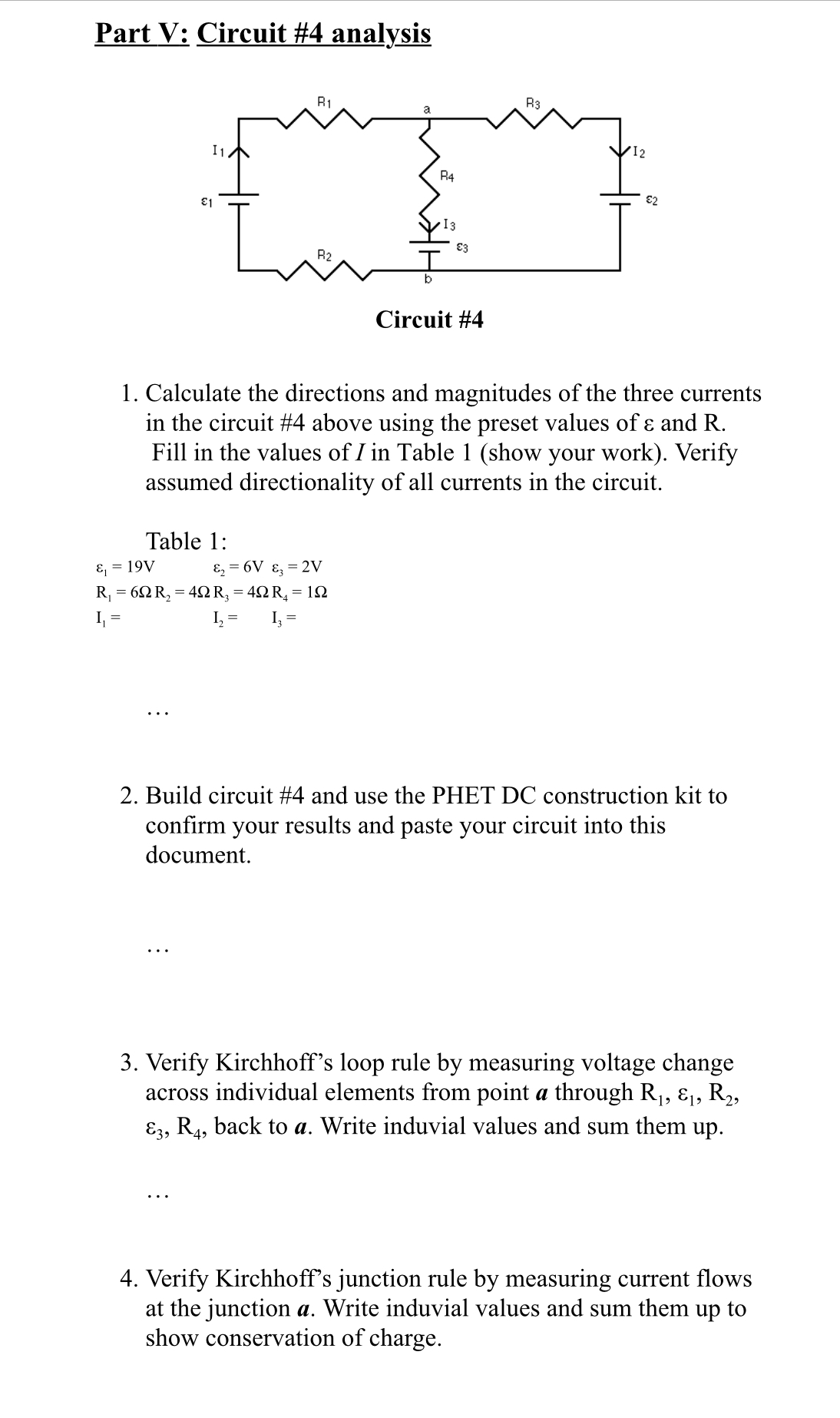
1.
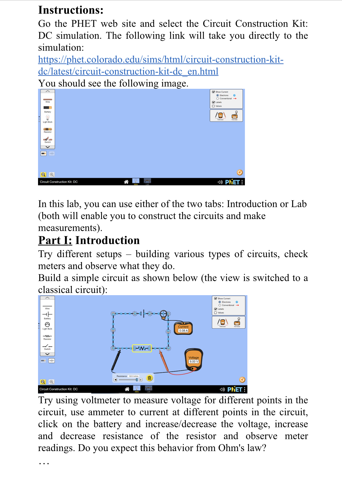
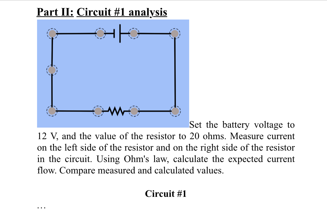
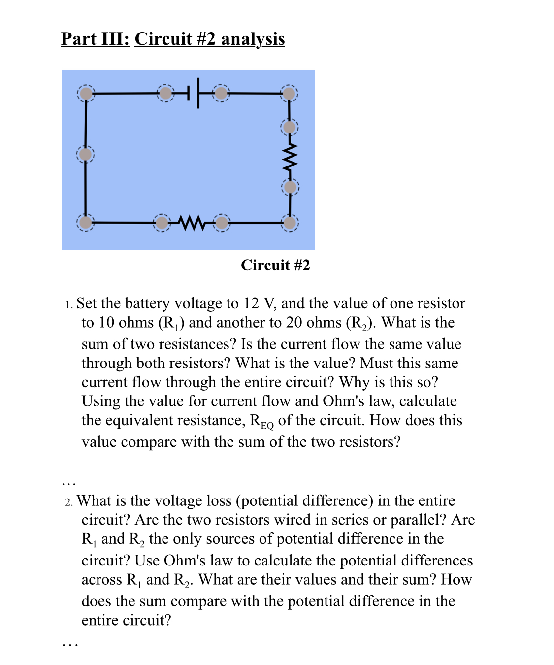
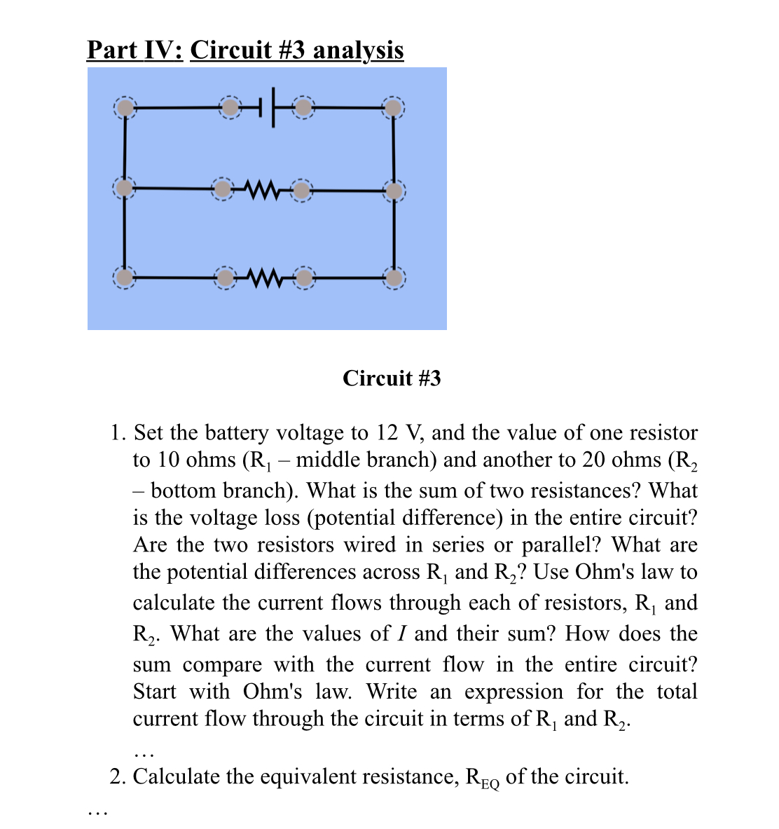
Instructions: Go the PHET web site and select the Circuit Construction Kit: DC simulation. The following link will take you directly to the simulation: h_ttpL//phet.colorado.edu/sims/htrnl/circuitconstruction-kit- dc/1atest/circuitconstruction-kitdc_en.html You should see the followin_ ' In this lab, you can use either of the two tabs: Introduction or Lab (both will enable you to construct the circuits and make measurements). Part I: Introduction Try different setups building various types of circuits, check meters and observe what they do. Build a simple circuit as shown below (the View is switched to a classical circuit : iii ' ' II- Try using voltmeter to measure voltage for different points in the circuit, use ammeter to current at different points in the circuit, click on the battery and increase/decrease the voltage, increase and decrease resistance of the resistor and observe meter readings. Do you expect this behavior from Ohm's law? Part 11: Circuit #1 analys_is Set the battery voltage to 12 V, and the value of the resistor to 20 ohms. Measure current on the left side of the resistor and on the right side of the resistor in the circuit. Using Ohm's law, calculate the expected current ow. Compare measured and calculated values. Circuit #1 Part III: Circuit #2 analysis Circuit #2 1. Set the battery voltage to 12 V, and the value of one resistor to 10 ohms (R1) and another to 20 ohms (R2). What is the sum of two resistances? Is the current flow the same value through both resistors? What is the value? Must this same current ow through the entire circuit? Why is this so? Using the value for current ow and Ohm's law, calculate the equivalent resistance, REQ of the circuit. How does this value compare with the sum of the two resistors? 2. What is the voltage loss (potential difference) in the entire circuit? Are the two resistors wired in series or parallel? Are R1 and R2 the only sources of potential difference in the circuit? Use Ohm's law to calculate the potential differences across R1 and R2. What are their values and their sum? How does the sum compare with the potential difference in the entire circuit? Part IV: Circuit #3 analys_is Circuit #3 1. Set the battery voltage to 12 V, and the value of one resistor to 10 ohms (R1 middle branch) and another to 20 ohms (R2 bottom branch). What is the sum of two resistances? What is the voltage loss (potential difference) in the entire circuit? Are the two resistors wired in series or parallel? What are the potential differences across R1 and R2? Use Ohm's law to calculate the current ows through each of resistors, R1 and R2. What are the values of I and their sum? How does the sum compare with the current ow in the entire circuit? Start with Ohm's law. Write an expression for the total current ow through the circuit in terms of R1 and R2. 2. Calculate the equivalent resistance, REQ of the circuit. Part V: Circuit #4 analysis E1 Circuit #4 1. Calculate the directions and magnitudes of the three currents in the circuit #4 above using the preset values of & and R. Fill in the values of I in Table 1 (show your work). Verify assumed directionality of all currents in the circuit. Table 1: &, = 19V E2 = 6V &, = 2V R, = 60R, = 40 R, = 40R, = 10 I = I, = I, = 2. Build circuit #4 and use the PHET DC construction kit to confirm your results and paste your circuit into this document. 3. Verify Kirchhoff's loop rule by measuring voltage change across individual elements from point a through R,, &1, R2, 83, R4, back to a. Write induvial values and sum them up. 4. Verify Kirchhoff's junction rule by measuring current flows at the junction a. Write induvial values and sum them up to show conservation of charge
