Answered step by step
Verified Expert Solution
Question
1 Approved Answer
1. What physical system do the equipotential lines you got resemble the best? (i.e. is it a point charge, a parallel plate capacitor, a


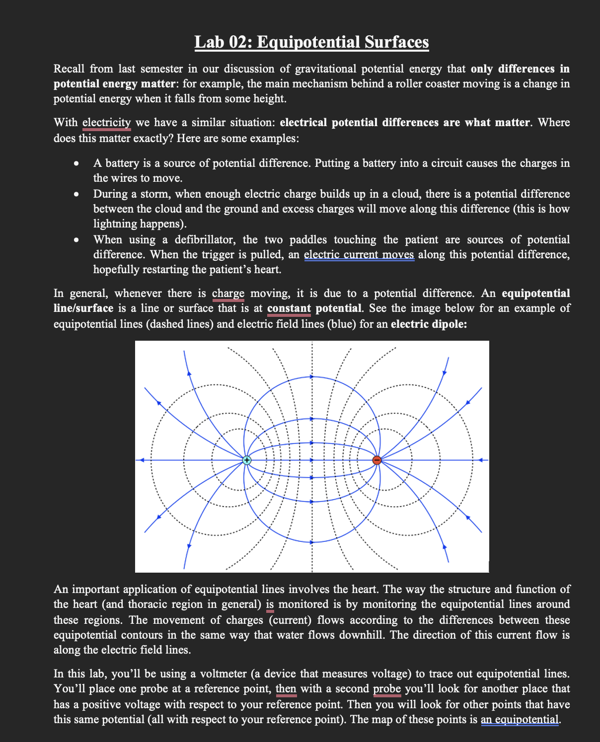
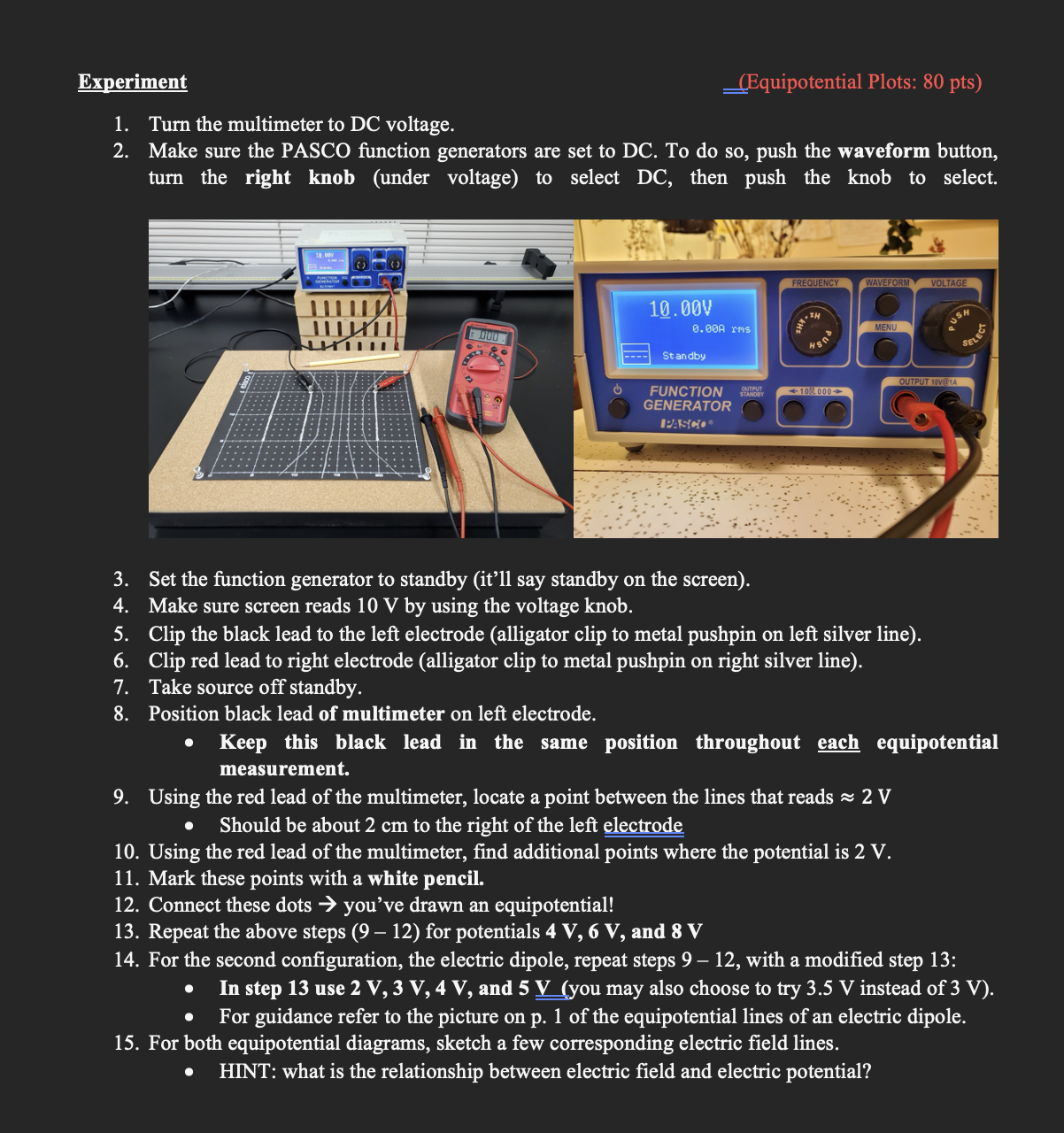
1. What physical system do the equipotential lines you got resemble the best? (i.e. is it a point charge, a parallel plate capacitor, a dipole, etc.) (10 pts) 1. 2. 2. Is your picture symmetric? Does this make sense? Why or why not? (10 pts) Lab 02: Equipotential Surfaces Recall from last semester in our discussion of gravitational potential energy that only differences in potential energy matter: for example, the main mechanism behind a roller coaster moving is a change in potential energy when it falls from some height. With electricity we have a similar situation: electrical potential differences are what matter. Where does this matter exactly? Here are some examples: A battery is a source of potential difference. Putting a battery into a circuit causes the charges in the wires to move. During a storm, when enough electric charge builds up in a cloud, there is a potential difference between the cloud and the ground and excess charges will move along this difference (this is how lightning happens). When using a defibrillator, the two paddles touching the patient are sources of potential difference. When the trigger is pulled, an electric current moves along this potential difference, hopefully restarting the patient's heart. In general, whenever there is charge moving, it is due to a potential difference. An equipotential line/surface is a line or surface that is at constant potential. See the image below for an example of equipotential lines (dashed lines) and electric field lines (blue) for an electric dipole: An important application of equipotential lines involves the heart. The way the structure and function of the heart (and thoracic region in general) is monitored is by monitoring the equipotential lines around these regions. The movement of charges (current) flows according to the differences between these equipotential contours in the same way that water flows downhill. The direction of this current flow is along the electric field lines. In this lab, you'll be using a voltmeter (a device that measures voltage) to trace out equipotential lines. You'll place one probe at a reference point, then with a second probe you'll look for another place that has a positive voltage with respect to your reference point. Then you will look for other points that have this same potential (all with respect to your reference point). The map of these points is an equipotential. Experiment 1. Turn the multimeter to DC voltage. (Equipotential Plots: 80 pts) 2. Make sure the PASCO function generators are set to DC. To do so, push the waveform button, turn the right knob (under voltage) to select DC, then push the knob to select. FREQUENCY WAVEFORM VOLTAGE 10.00V TH 0.00A rms MENU DOO Standby OUTPUT 10V@1A FUNCTION STANDBY GENERATOR PASCO 100.000 PUSH SELECT 3. Set the function generator to standby (it'll say standby on the screen). 4. Make sure screen reads 10 V by using the voltage knob. 5. Clip the black lead to the left electrode (alligator clip to metal pushpin on left silver line). 6. Clip red lead to right electrode (alligator clip to metal pushpin on right silver line). 7. Take source off standby. 8. Position black lead of multimeter on left electrode. Keep this black lead in the same position throughout each equipotential measurement. 9. Using the red lead of the multimeter, locate a point between the lines that reads 2 V Should be about 2 cm to the right of the left electrode 10. Using the red lead of the multimeter, find additional points where the potential is 2 V. 11. Mark these points with a white pencil. 12. Connect these dots you've drawn an equipotential! - 13. Repeat the above steps (9 12) for potentials 4 V, 6 V, and 8 V 14. For the second configuration, the electric dipole, repeat steps 9 12, with a modified step 13: In step 13 use 2 V, 3 V, 4 V, and 5 V (you may also choose to try 3.5 V instead of 3 V). For guidance refer to the picture on p. 1 of the equipotential lines of an electric dipole. 15. For both equipotential diagrams, sketch a few corresponding electric field lines. . HINT: what is the relationship between electric field and electric potential?
Step by Step Solution
There are 3 Steps involved in it
Step: 1

Get Instant Access to Expert-Tailored Solutions
See step-by-step solutions with expert insights and AI powered tools for academic success
Step: 2

Step: 3

Ace Your Homework with AI
Get the answers you need in no time with our AI-driven, step-by-step assistance
Get Started


