

Answered step by step
Verified Expert Solution
Question
1 Approved Answer
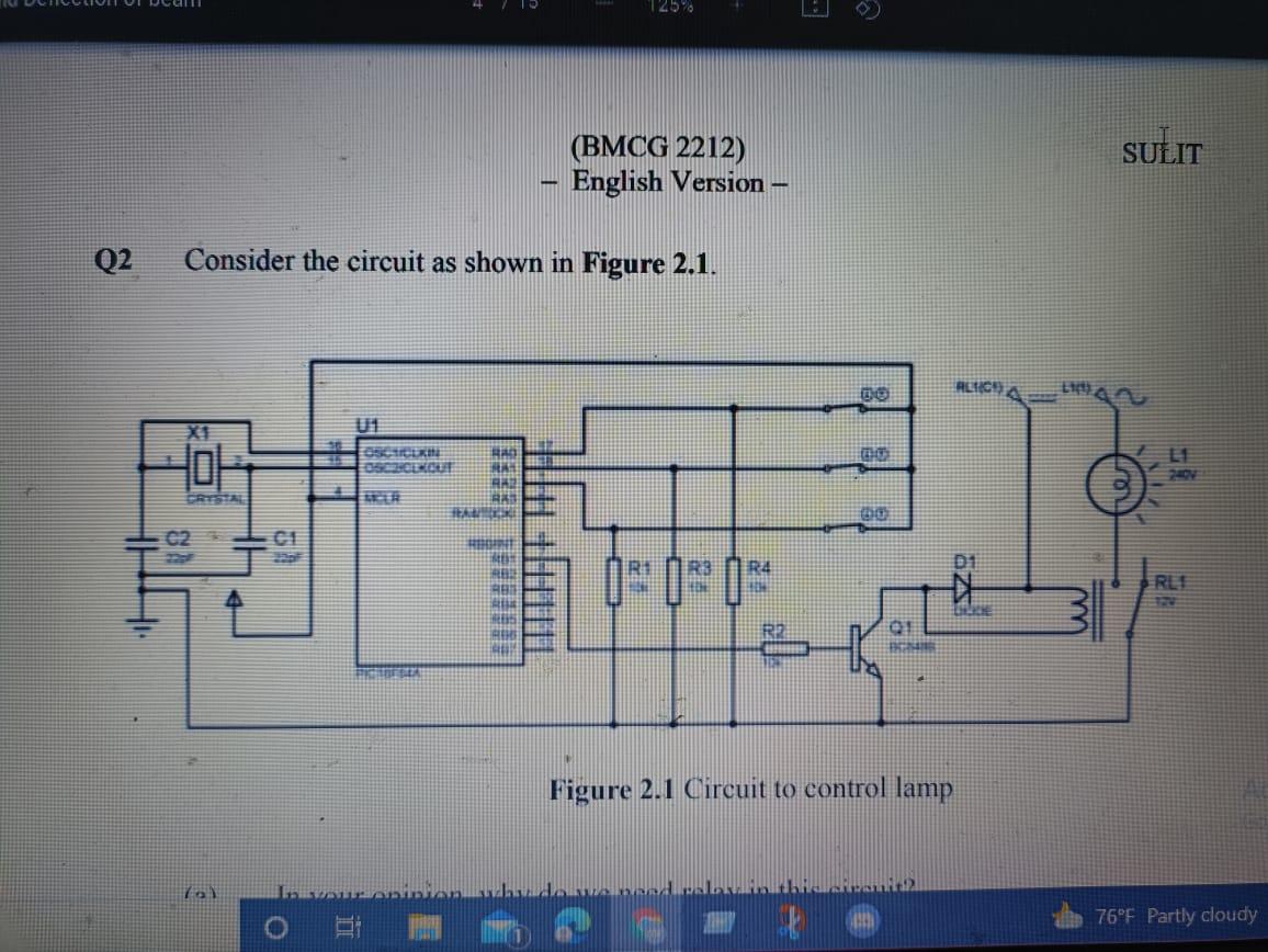
125% SULIT (BMCG 2212) - English Version - Q2 Consider the circuit as shown in Figure 2.1. DO AL109 RAD -0- OSOBE KOUT RA TER
Step by Step Solution
There are 3 Steps involved in it
Step: 1

Get Instant Access to Expert-Tailored Solutions
See step-by-step solutions with expert insights and AI powered tools for academic success
Step: 2

Step: 3
Ace Your Homework with AI
Get the answers you need in no time with our AI-driven, step-by-step assistance
Get Started
Data Management Databases And Organizations
Authors: Richard T. Watson
2nd Edition
0471180742, 978-0471180746