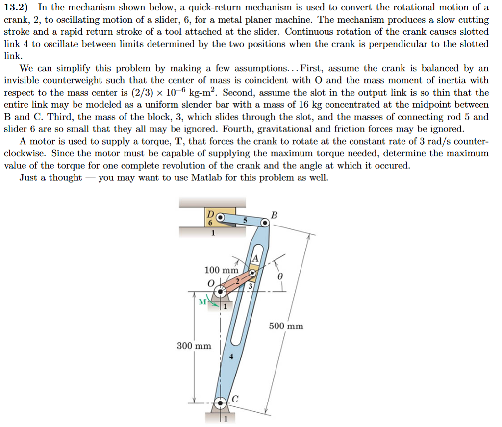
13.2) In the mechanism shown below, a quick-return mechanism is used to convert the rotational motion of a crank, 2, to oscillating motion of a slider, 6, for a metal planer machine. The mechanism produces a slow cutting stroke and a rapid return stroke of a tool attached at the slider. Continuous rotation of the crank causcs slotted link 4 to oscillate between limits determined by the two positions when the crank is perpendicular to the slotted link We can simplify this problem by making a few assumptions... First, assume the crank is balanced by an invisible counterweight such that the center of mass is coincident with O and the mass moment of inertia witlh respect to the mass center is (2/3) 10 6 kg-m2. Second, assume the slot in the output link is so thin that the entire link may be modeled as a uniform slender bar with a mass of 16 kg concentrated at the midpoint between B and C. Third, the mass of the block, 3, which slides through the slot, and the masses of connecting rod 5 and slider 6 are so small that they all may be ignored. Fourth, gravitational and friction forces may be ignored A motor is used to supply a torque, T, that forces the crank to rotate at the constant rate of 3 rad/s counter- clockwise. Since the motor must be capable of supplying the maximum torque needed, determine the maximum value of the torque for one complete revolution of the crank and the angle at which it occured Just a thought - you may want to use Matlab for this problem as well. 100 mm 500 mm 300 mm 13.2) In the mechanism shown below, a quick-return mechanism is used to convert the rotational motion of a crank, 2, to oscillating motion of a slider, 6, for a metal planer machine. The mechanism produces a slow cutting stroke and a rapid return stroke of a tool attached at the slider. Continuous rotation of the crank causcs slotted link 4 to oscillate between limits determined by the two positions when the crank is perpendicular to the slotted link We can simplify this problem by making a few assumptions... First, assume the crank is balanced by an invisible counterweight such that the center of mass is coincident with O and the mass moment of inertia witlh respect to the mass center is (2/3) 10 6 kg-m2. Second, assume the slot in the output link is so thin that the entire link may be modeled as a uniform slender bar with a mass of 16 kg concentrated at the midpoint between B and C. Third, the mass of the block, 3, which slides through the slot, and the masses of connecting rod 5 and slider 6 are so small that they all may be ignored. Fourth, gravitational and friction forces may be ignored A motor is used to supply a torque, T, that forces the crank to rotate at the constant rate of 3 rad/s counter- clockwise. Since the motor must be capable of supplying the maximum torque needed, determine the maximum value of the torque for one complete revolution of the crank and the angle at which it occured Just a thought - you may want to use Matlab for this problem as well. 100 mm 500 mm 300 mm