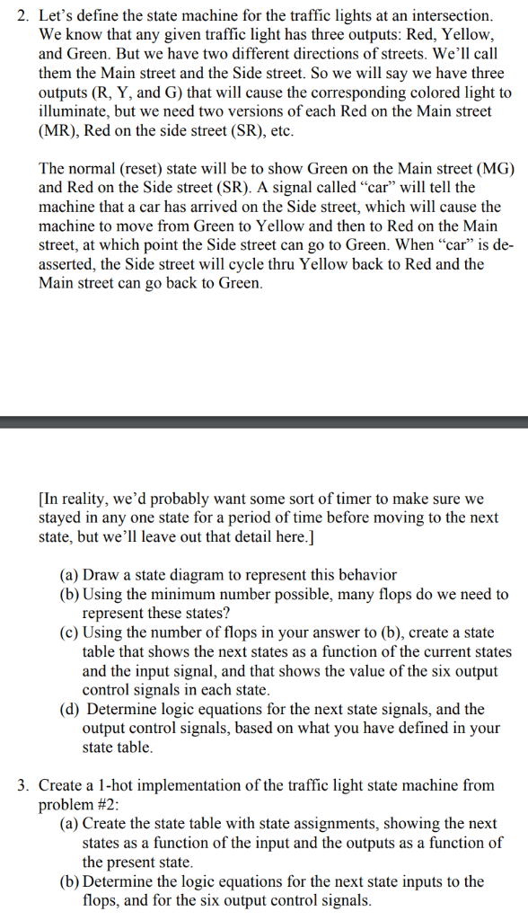
2. Let's define the state machine for the traffic lights at an intersection We know that any given traffic light has three outputs: Red, Yellow, and Green. But we have two different directions of streets. We'll call them the Main street and the Side street. So we will say we have three outputs (R, Y, and G) that will cause the corresponding colored light to illuminate, but we need two versions of each Red on the Main street (MR), Red on the side street (SR), etc The normal (reset) state will be to show Green on the Main street (MG) and Red on the Side street (SR). A signal called "car" will tell the machine that a car has arrived on the Side street, which will cause the machine to move from Green to Yellow and then to Red on the Main street, at which point the Side street can go to Green. When "car" is de asserted, the Side street will cycle thru Yellow back to Red and the Main street can go back to Greern [In reality, we'd probably want some sort of timer to make sure we stayed in any one state for a period of time before moving to the next state, but we'll leave out that detail here.] (a) Draw a state diagram to represent this behavior (b) Using the minimum number possible, many flops do we need to represent these states? (c) Using the number of flops in your answer to (b), create a state table that shows the next states as a function of the current states and the input signal, and that shows the value of the six output control signals in each state (d) Determine logic equations for the next state signals, and the output control signals, based on what you have defined in your state table 3. Create a 1-hot implementation of the traffic light state machine fronm problem #2 (a) Create the state table with state assignments, showing the next states as a function of the input and the outputs as a function of the present state (b) Determine the logic equations for the next state inputs to the flops, and for the six output control signals 2. Let's define the state machine for the traffic lights at an intersection We know that any given traffic light has three outputs: Red, Yellow, and Green. But we have two different directions of streets. We'll call them the Main street and the Side street. So we will say we have three outputs (R, Y, and G) that will cause the corresponding colored light to illuminate, but we need two versions of each Red on the Main street (MR), Red on the side street (SR), etc The normal (reset) state will be to show Green on the Main street (MG) and Red on the Side street (SR). A signal called "car" will tell the machine that a car has arrived on the Side street, which will cause the machine to move from Green to Yellow and then to Red on the Main street, at which point the Side street can go to Green. When "car" is de asserted, the Side street will cycle thru Yellow back to Red and the Main street can go back to Greern [In reality, we'd probably want some sort of timer to make sure we stayed in any one state for a period of time before moving to the next state, but we'll leave out that detail here.] (a) Draw a state diagram to represent this behavior (b) Using the minimum number possible, many flops do we need to represent these states? (c) Using the number of flops in your answer to (b), create a state table that shows the next states as a function of the current states and the input signal, and that shows the value of the six output control signals in each state (d) Determine logic equations for the next state signals, and the output control signals, based on what you have defined in your state table 3. Create a 1-hot implementation of the traffic light state machine fronm problem #2 (a) Create the state table with state assignments, showing the next states as a function of the input and the outputs as a function of the present state (b) Determine the logic equations for the next state inputs to the flops, and for the six output control signals


