Answered step by step
Verified Expert Solution
Question
1 Approved Answer
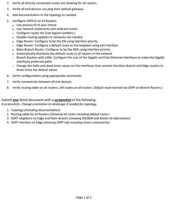
2. Verify all directly connected routes are showing for all routers. 3. Verify all end devices can ping their default gateway. 4. Add documentation


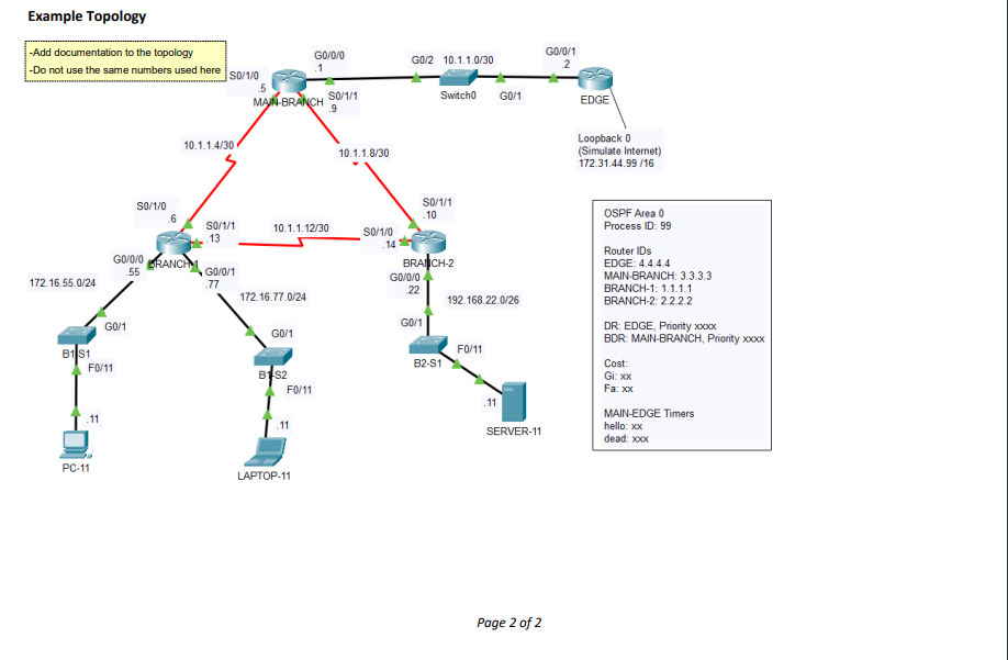
2. Verify all directly connected routes are showing for all routers. 3. Verify all end devices can ping their default gateway. 4. Add documentation to the topology as needed. 5. Configure OSPFv2 on all Routers: a. Use process ID of your choice b. Use network statements and wildcard masks c. Configure router IDs (Use logical numbers.) d. Disable routing updates to networks not needed e. Edge Router: Configure to be the DR using interface priority f. Edge Router: Configure a default route to the loopback using exit interface g. Main-Branch Router: Configure to be the BDR using interface priority h. Automatically distribute the default route to all routers in the network i. Branch Routers with LANs: Configure the cost of the Gigabit and Fast Ethernet interfaces to make the Gigabit interfaces preferred paths j. Change the hello and dead timer values on the interfaces that connect the Main Branch and Edge routers to three times the default values 6. Verify configurations using appropriate commands. 7. Verify connectivity between all end devices. 8. Verify routing table on all routers. (All routes on all routers. Default route learned via OSPF on Branch Routers.) Submit one Word document with a screenshot of the following: 8 screenshots. Change orientation to landscape if needed for topology. 1. Topology (including documentation) 2. Routing table for all Routers (Showing all routes including default route.) 3. OSPF neighbors on Edge and Main-Branch (showing DR/BDR and Router ID information) 4. OSPF interface on Edge (showing OSPF info including timers and priority) Page 1 of 2 Example Topology -Add documentation to the topology -Do not use the same numbers used here 172.16.55.0/24 G0/0/0 1 GO/2 10.1.1.0/30 S0/1/0 .5 MAIN-BRANCH S0/1/1 .9 10.1.1.4/30 10.1.1.8/30 Switch0 G0/1 S0/1/0 .6 S0/1/1 .10 S0/1/1 .13 10.1.1.12/30 S0/1/0 .14 G0/0/0 BRANCH BRANCH-2 55 G0/0/1 .77 G0/0/0 22 172.16.77.0/24 192.168.22.0/26 G0/1 G0/1 G0/1 B1 S1 F0/11 .11 F0/11 B2-S1 B1S2 F0/11 .11 PC-11 LAPTOP-11 SERVER-11 Page 2 of 2 G0/0/1 .2 EDGE Loopback 0 (Simulate Internet) 172.31.44.99/16 OSPF Area 0 Process ID: 99 Router IDs EDGE: 4.4.4.4 MAIN-BRANCH: 3.3.3.3 BRANCH-1: 1.1.1.1 BRANCH-2: 2.2.2.2 DR: EDGE, Priority xxxxx BDR: MAIN-BRANCH, Priority xxxx Cost: Gi: xx Fa: xx MAIN-EDGE Timers hello: xx dead: xxxx
Step by Step Solution
There are 3 Steps involved in it
Step: 1

Get Instant Access to Expert-Tailored Solutions
See step-by-step solutions with expert insights and AI powered tools for academic success
Step: 2

Step: 3

Ace Your Homework with AI
Get the answers you need in no time with our AI-driven, step-by-step assistance
Get Started


