Question
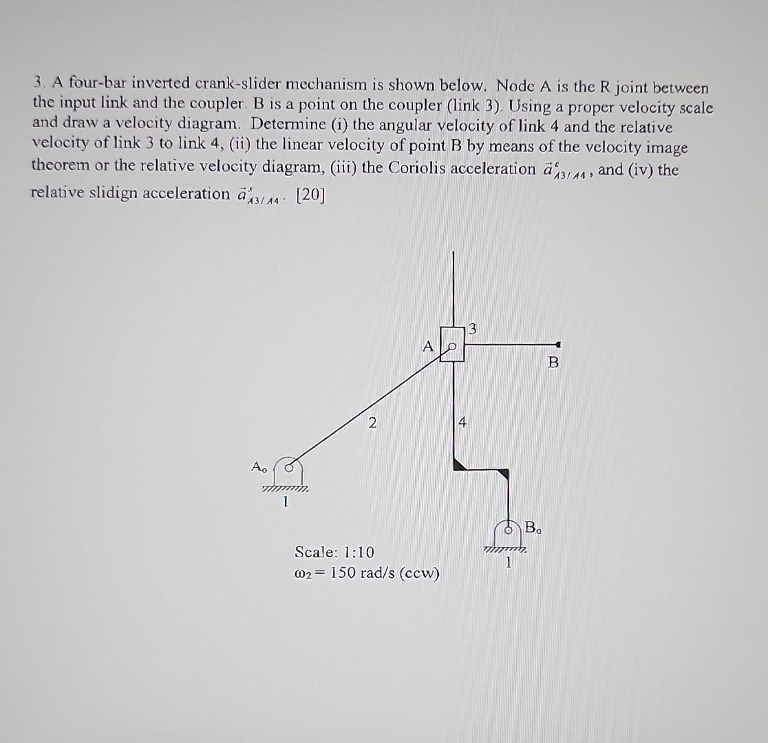
3. A four-bar inverted crank-slider mechanism is shown below. Node A is the R joint between the input link and the coupler. B is

3. A four-bar inverted crank-slider mechanism is shown below. Node A is the R joint between the input link and the coupler. B is a point on the coupler (link 3). Using a proper velocity scale and draw a velocity diagram. Determine (i) the angular velocity of link 4 and the relative velocity of link 3 to link 4, (ii) the linear velocity of point B by means of the velocity image theorem or the relative velocity diagram, (iii) the Coriolis acceleration a43/44, and (iv) the relative slidign acceleration a3/44 [20] Ao 1 2 A Scale: 1:10 @2 150 rad/s (ccw) 4 3 1 Ba B
Step by Step Solution
There are 3 Steps involved in it
Step: 1

Get Instant Access to Expert-Tailored Solutions
See step-by-step solutions with expert insights and AI powered tools for academic success
Step: 2

Step: 3

Ace Your Homework with AI
Get the answers you need in no time with our AI-driven, step-by-step assistance
Get StartedRecommended Textbook for
Income Tax Fundamentals 2013
Authors: Gerald E. Whittenburg, Martha Altus Buller, Steven L Gill
31st Edition
1111972516, 978-1285586618, 1285586611, 978-1285613109, 978-1111972516
Students also viewed these Mechanical Engineering questions
Question
Answered: 1 week ago
Question
Answered: 1 week ago
Question
Answered: 1 week ago
Question
Answered: 1 week ago
Question
Answered: 1 week ago
Question
Answered: 1 week ago
Question
Answered: 1 week ago
Question
Answered: 1 week ago
Question
Answered: 1 week ago
Question
Answered: 1 week ago
Question
Answered: 1 week ago
Question
Answered: 1 week ago
Question
Answered: 1 week ago
Question
Answered: 1 week ago
Question
Answered: 1 week ago
Question
Answered: 1 week ago
Question
Answered: 1 week ago
Question
Answered: 1 week ago
Question
Answered: 1 week ago
Question
Answered: 1 week ago
View Answer in SolutionInn App


