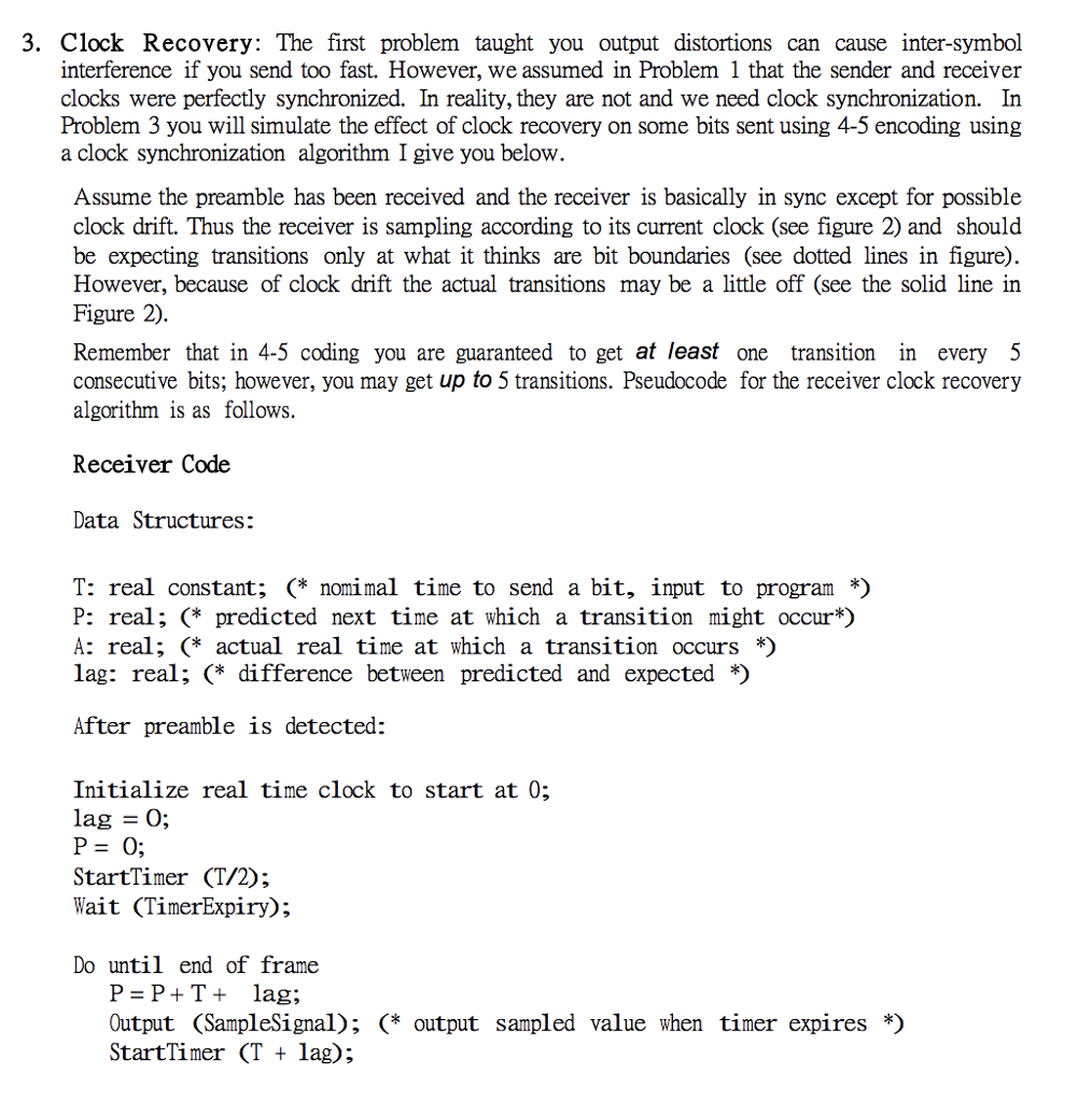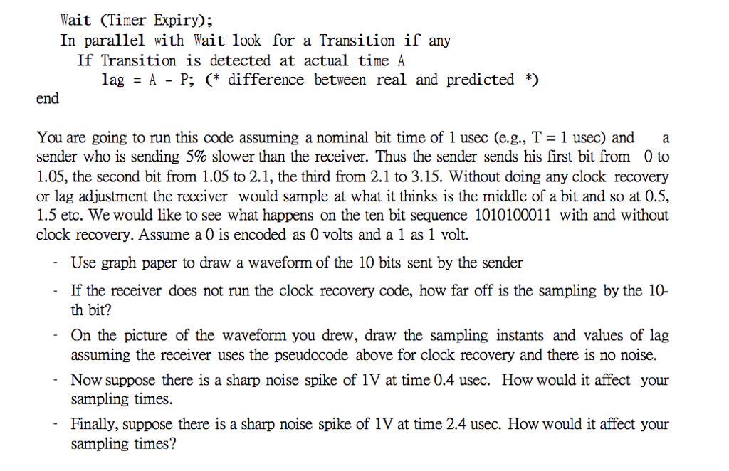

3. Clock Recovery: The first problem taught you output distortions can cause inter-symbol interference if you send too fast. However, we assumed in Problem 1 that the sender and receiver clocks were perfectly synchronized. In reality, they are not and we need clock synchronization. In Problem 3 you will simulate the effect of clock recovery on some bits sent using 4-5 encoding using a clock synchronization algorithm I give you below Assume the preamble has been received and the receiver is basically in sync except for possible clock drift. Thus the receiver is sampling according to its current clock (see figure 2) and shoulod be expecting transitions only at what it thinks are bit boundaries (see dotted lines in figure). However, because of clock drift the actual transitions may be a little off (see the solid line in Figure 2). Remember that in 4-5 coding you are guaranteed to get at least one transition in every 5 consecutive bits; however, you may get up to 5 transitions. Pseudocode for the receiver clock recovery algorithm is as follows. Receiver Code Data Structures: T: real constant; (* nomimal time to send a bit, input to program *) P: real; (* predicted next time at which a transition might occur*) A: real; (* actual real time at which a transition occurs *) lag: real; (* difference between predicted and expected *) After preamble is detected: Initialize real time clock to start at 0; lag O; StartTimer (T/2); Wait (TimerExpiry); Do until end of frame P PT+ lag; Output (SampleSignal); (* output sampled value when timer expires *) StartTimer (T + lag); 3. Clock Recovery: The first problem taught you output distortions can cause inter-symbol interference if you send too fast. However, we assumed in Problem 1 that the sender and receiver clocks were perfectly synchronized. In reality, they are not and we need clock synchronization. In Problem 3 you will simulate the effect of clock recovery on some bits sent using 4-5 encoding using a clock synchronization algorithm I give you below Assume the preamble has been received and the receiver is basically in sync except for possible clock drift. Thus the receiver is sampling according to its current clock (see figure 2) and shoulod be expecting transitions only at what it thinks are bit boundaries (see dotted lines in figure). However, because of clock drift the actual transitions may be a little off (see the solid line in Figure 2). Remember that in 4-5 coding you are guaranteed to get at least one transition in every 5 consecutive bits; however, you may get up to 5 transitions. Pseudocode for the receiver clock recovery algorithm is as follows. Receiver Code Data Structures: T: real constant; (* nomimal time to send a bit, input to program *) P: real; (* predicted next time at which a transition might occur*) A: real; (* actual real time at which a transition occurs *) lag: real; (* difference between predicted and expected *) After preamble is detected: Initialize real time clock to start at 0; lag O; StartTimer (T/2); Wait (TimerExpiry); Do until end of frame P PT+ lag; Output (SampleSignal); (* output sampled value when timer expires *) StartTimer (T + lag)


