Answered step by step
Verified Expert Solution
Question
1 Approved Answer
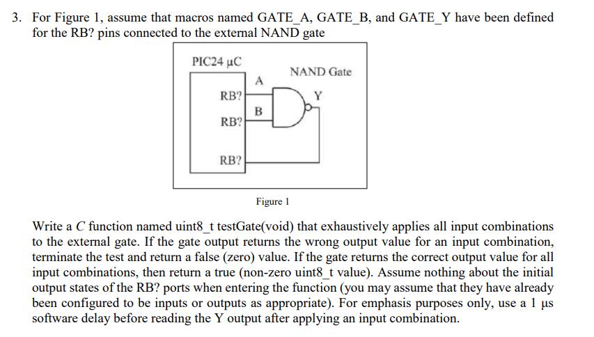
3. For Figure 1, assume that macros named GATE_A, GATE_B, and GATE_Y have been defined for the RB? pins connected to the external NAND

3. For Figure 1, assume that macros named GATE_A, GATE_B, and GATE_Y have been defined for the RB? pins connected to the external NAND gate PIC24 C NAND Gate A RB? Y B RB? RB? Figure 1 Write a C function named uint8_t testGate(void) that exhaustively applies all input combinations to the external gate. If the gate output returns the wrong output value for an input combination, terminate the test and return a false (zero) value. If the gate returns the correct output value for all input combinations, then return a true (non-zero uint8_t value). Assume nothing about the initial output states of the RB? ports when entering the function (you may assume that they have already been configured to be inputs or outputs as appropriate). For emphasis purposes only, use a 1 us software delay before reading the Y output after applying an input combination.
Step by Step Solution
There are 3 Steps involved in it
Step: 1
Heres a C function named testGate that fulfills your req...
Get Instant Access to Expert-Tailored Solutions
See step-by-step solutions with expert insights and AI powered tools for academic success
Step: 2

Step: 3

Ace Your Homework with AI
Get the answers you need in no time with our AI-driven, step-by-step assistance
Get Started


