

Answered step by step
Verified Expert Solution
Question
1 Approved Answer
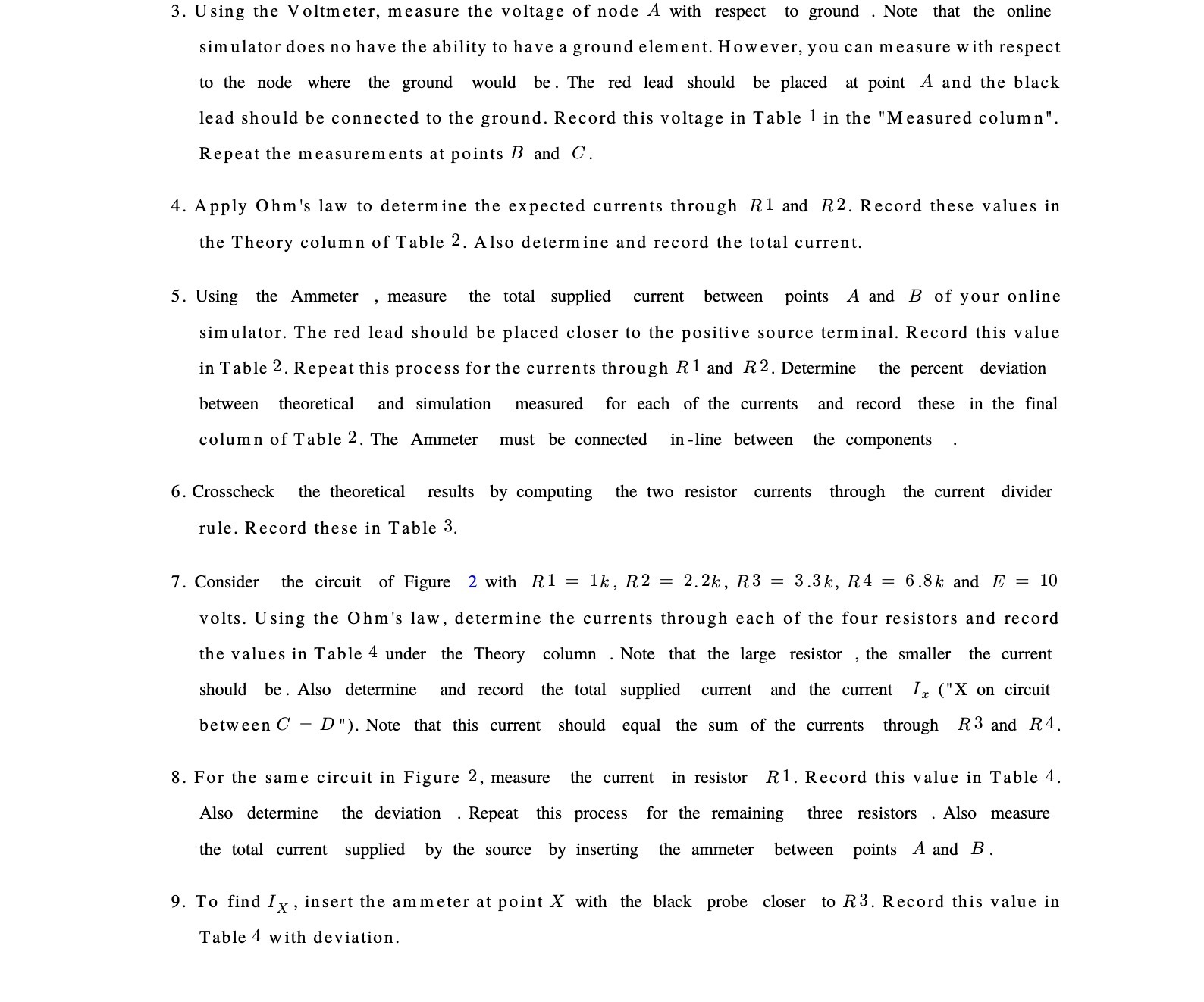
3. Using the Voltmeter, measure the voltage of node A with respect to ground . Note that the online simulator does no have the ability
Step by Step Solution
There are 3 Steps involved in it
Step: 1

Get Instant Access to Expert-Tailored Solutions
See step-by-step solutions with expert insights and AI powered tools for academic success
Step: 2

Step: 3
Ace Your Homework with AI
Get the answers you need in no time with our AI-driven, step-by-step assistance
Get Started
College Physics A Strategic Approach Volume 1
Authors: Randall D. Knight, Brian Jones, Stuart Field
2nd Edition
0321602285, 978-0321602282