

Answered step by step
Verified Expert Solution
Question
1 Approved Answer
4 exercise Find Your scheme according to Table No . 3 and pictures. Redraw the scheme according to the requirements. Describe in detail the operating
exercise
Find Your scheme according to Table No and pictures. Redraw the scheme according to the requirements.
Describe in detail the operating principles of the given power drive: working stroke without the load, with load,
return stroke short description is given
Table No
scheme
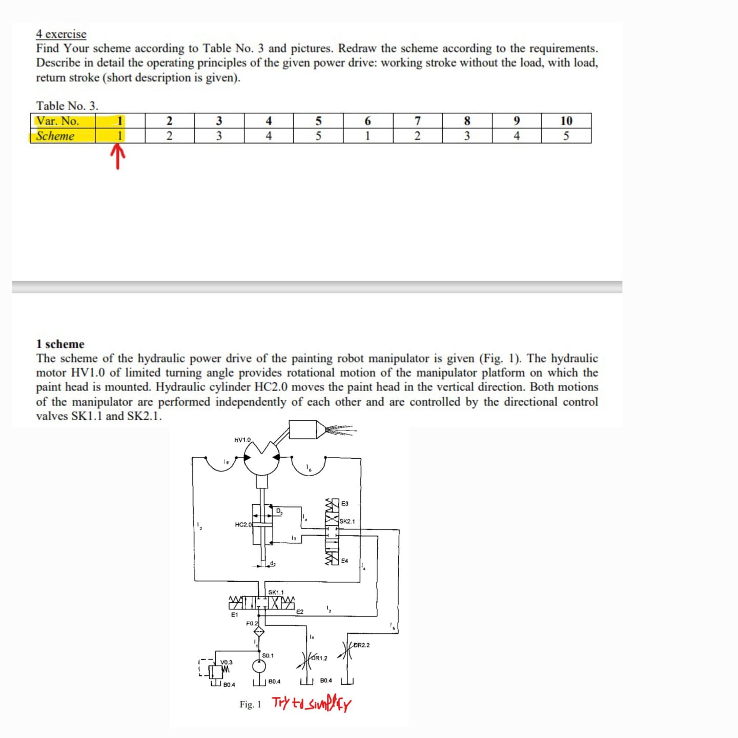
The scheme of the hydraulic power drive of the painting robot manipulator is given Fig The hydraulic
motor HV of limited turning angle provides rotational motion of the manipulator platform on which the
paint head is mounted. Hydraulic cylinder HC moves the paint head in the vertical direction. Both motions
of the manipulator are performed independently of each other and are controlled by the directional control
valves SK and SK
Step by Step Solution
There are 3 Steps involved in it
Step: 1

Get Instant Access to Expert-Tailored Solutions
See step-by-step solutions with expert insights and AI powered tools for academic success
Step: 2

Step: 3
Ace Your Homework with AI
Get the answers you need in no time with our AI-driven, step-by-step assistance
Get Started
Heat Transfer
Authors: Jack Holman
10th edition
73529362, 978-0073529363