Answered step by step
Verified Expert Solution
Question
1 Approved Answer
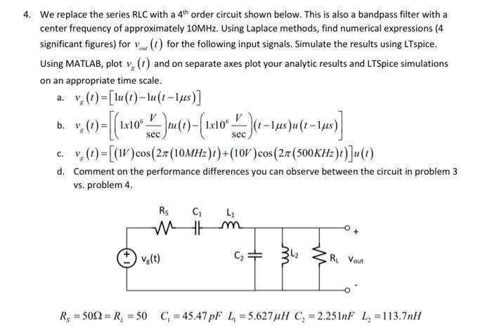
4. We replace the series RLC with a 4th order circuit shown below. This is also a bandpass filter with a center frequency of

4. We replace the series RLC with a 4th order circuit shown below. This is also a bandpass filter with a center frequency of approximately 10MHz. Using Laplace methods, find numerical expressions (4 significant figures) for Vou (1) for the following input signals. Simulate the results using LTspice. Using MATLAB, plot v (1) and on separate axes plot your analytic results and LTSpice simulations on an appropriate time scale. v (t)=[lu(t)-lu(t-lus)] b. v v. (1)=[{1x10 ]tu (1)-({1x10 )(1-15)u(1-1,15)] sec a. sec C. c. v. (1)= [(IV) cos(27 (10MHz)t) + (10V) cos (27 (500KHz)t)]u (1) d. Comment on the performance differences you can observe between the circuit in problem 3 vs. problem 4. Rs C L M Im Vg(t) C: R Vout R = 5002= R = 50 C=45.47 pF L = 5.627 uH C = 2.251nF L=113.7nH
Step by Step Solution
★★★★★
3.31 Rating (151 Votes )
There are 3 Steps involved in it
Step: 1
a vit ut uts Step 1 Find the Laplace Transform of the Input Signal The Laplace transform of the inpu...
Get Instant Access to Expert-Tailored Solutions
See step-by-step solutions with expert insights and AI powered tools for academic success
Step: 2

Step: 3

Ace Your Homework with AI
Get the answers you need in no time with our AI-driven, step-by-step assistance
Get Started


